DCN Wireless Installation and User Instructions System Design and Planning
en 23
3.5.3Power supply
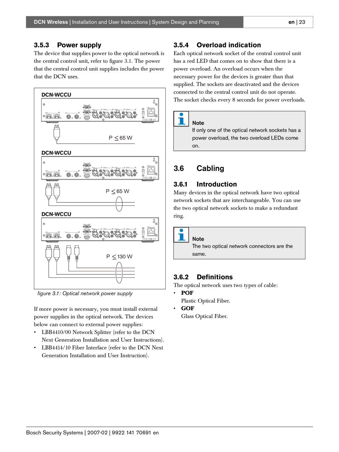
The device that supplies power to the optical network is the central control unit, refer to figure 3.1. The power that the central control unit supplies includes the power that the DCN uses.
|
|
|
|
|
|
|
| |||
|
|
| RS 232 | Port 1 |
|
|
|
|
|
|
|
|
|
|
|
|
|
|
| Mains |
|
|
|
| RS 232 | Port 2 | Audio In 1 | Audio Out 1 | Audio In 2 | Audio Out 2 |
|
|
Network |
| Trunk |
|
|
|
|
| 230 |
|
|
1 | 2 | 1 | 2 |
|
|
|
|
|
| |
|
|
| Fault |
|
|
|
|
|
|
|
|
|
| OK | Fault |
|
|
|
|
|
|
|
|
|
|
|
|
|
| 115: | T2.5A 250V | |
|
|
|
|
|
|
|
| 230: | T2A H 250V | |
|
|
|
|
|
|
| P < 65 W |
|
| |
|
|
|
|
|
|
|
| |||
|
|
| RS 232 | Port 1 |
|
|
|
|
|
|
|
|
|
|
|
|
|
|
| Mains |
|
|
|
| RS 232 | Port 2 | Audio In 1 | Audio Out 1 | Audio In 2 | Audio Out 2 |
|
|
Network |
| Trunk |
|
|
|
|
| 230 |
|
|
1 | 2 | 1 | 2 |
|
|
|
|
|
| |
|
|
| Fault |
|
|
|
|
|
|
|
|
|
| OK | Fault |
|
|
|
|
|
|
|
|
|
|
|
|
|
| 115: | T2.5A 250V | |
|
|
|
|
|
|
|
| 230: | T2A H 250V | |
|
|
|
|
|
| P < 65 W |
|
| ||
|
|
|
|
|
|
|
| |||
|
|
| RS 232 | Port 1 |
|
|
|
|
|
|
|
|
|
|
|
|
|
|
| Mains |
|
|
|
| RS 232 | Port 2 | Audio In 1 | Audio Out 1 | Audio In 2 | Audio Out 2 |
|
|
Network |
| Trunk |
|
|
|
|
| 230 |
|
|
1 | 2 | 1 | 2 |
|
|
|
|
|
| |
|
|
| Fault |
|
|
|
|
|
|
|
|
|
| OK | Fault |
|
|
|
|
|
|
|
|
|
|
|
|
|
| 115: | T2.5A 250V | |
|
|
|
|
|
|
|
| 230: | T2A H 250V | |
|
|
|
|
|
| P < 130 W |
|
| ||
figure 3.1: Optical network power supply
If more power is necessary, you must install external power supplies in the optical network. The devices below can connect to external power supplies:
•LBB4410/00 Network Splitter (refer to the DCN Next Generation Installation and User Instructions).
•LBB4414/10 Fiber Interface (refer to the DCN Next Generation Installation and User Instruction).
3.5.4Overload indication
Each optical network socket of the central control unit has a red LED that comes on to show that there is a power overload. An overload occurs when the necessary power for the devices is greater than that supplied. The sockets are deactivated and the devices connected to the central control unit do not operate. The socket checks every 8 seconds for power overloads.
Note
If only one of the optical network sockets has a power overload, the two overload LEDs come on.
3.6Cabling
3.6.1Introduction
Many devices in the optical network have two optical network sockets that are interchangeable. You can use the two optical network sockets to make a redundant ring.
Note
The two optical network connectors are the same.
3.6.2Definitions
The optical network uses two types of cable:
•POF
Plastic Optical Fiber.
•GOF
Glass Optical Fiber.
Bosch Security Systems