DCN Wireless Installation and User Instructions Contribution Devices
15.3External connections
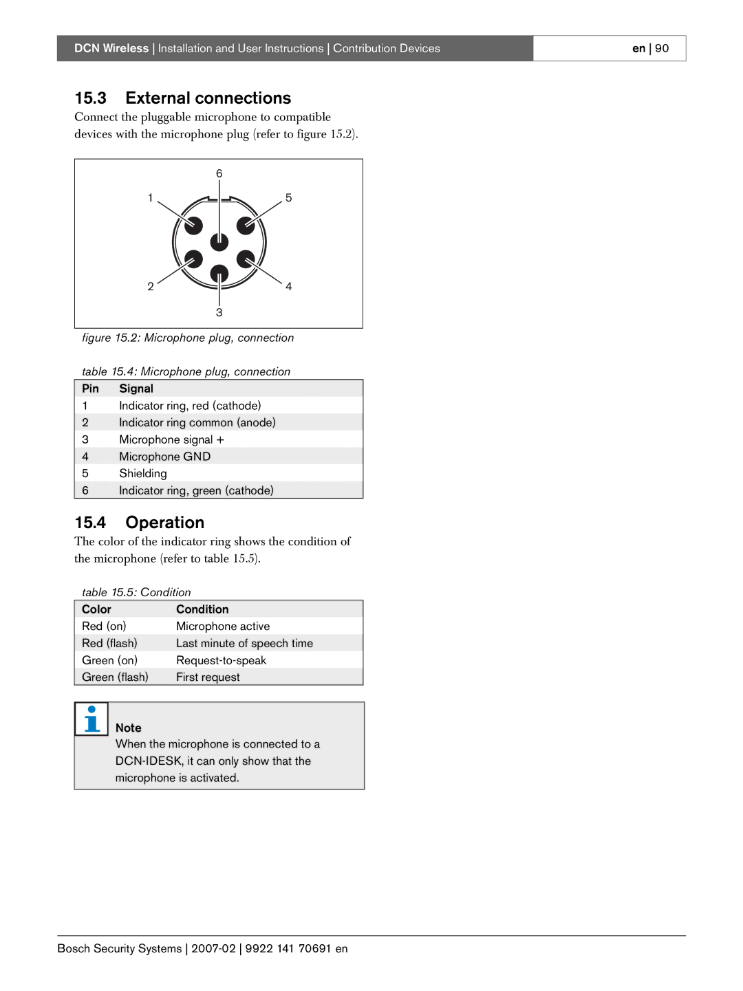
Connect the pluggable microphone to compatible devices with the microphone plug (refer to figure 15.2).
6
15
24
3
figure 15.2: Microphone plug, connection
table 15.4: Microphone plug, connection
Pin Signal
1Indicator ring, red (cathode)
2Indicator ring common (anode)
3 Microphone signal +
4 Microphone GND
5Shielding
6Indicator ring, green (cathode)
15.4Operation
The color of the indicator ring shows the condition of the microphone (refer to table 15.5).
table 15.5: Condition
Color | Condition |
Red (on) | Microphone active |
Red (flash) | Last minute of speech time |
Green (on) | |
Green (flash) | First request |
Note
When the microphone is connected to a
en 90