DCN Wireless Installation and User Instructions Contribution Devices
en 99
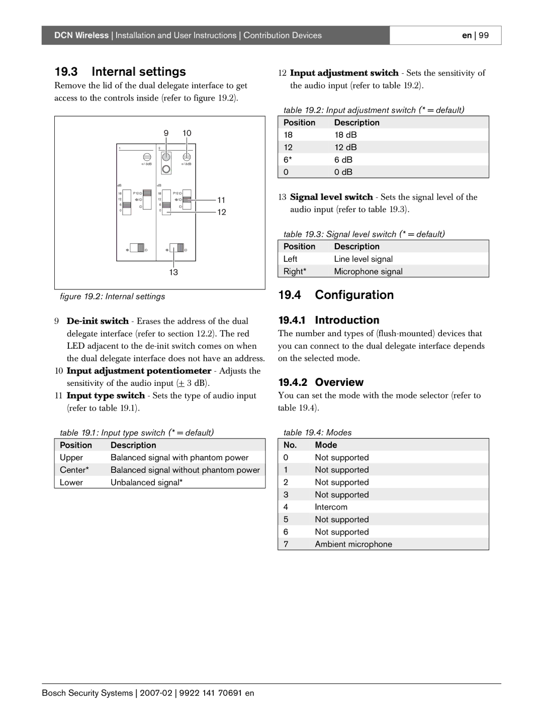
19.3Internal settings
Remove the lid of the dual delegate interface to get access to the controls inside (refer to figure 19.2).
|
| 9 |
| 10 |
1 |
| 2 |
|
|
|
|
| ||
dB |
| dB |
|
|
18 | P12 | 18 | P12 | 11 |
12 | / | 12 | / | |
6 |
| 6 |
|
|
00 ![]() 12
12
13
figure 19.2: Internal settings
9
10Input adjustment potentiometer - Adjusts the sensitivity of the audio input (+ 3 dB).
11Input type switch - Sets the type of audio input (refer to table 19.1).
table 19.1: Input type switch (* = default)
Position | Description |
Upper | Balanced signal with phantom power |
Center* | Balanced signal without phantom power |
Lower | Unbalanced signal* |
12Input adjustment switch - Sets the sensitivity of the audio input (refer to table 19.2).
table 19.2: Input adjustment switch (* = default)
Position Description
18 | 18 dB |
12 | 12 dB |
6* | 6 dB |
00 dB
13Signal level switch - Sets the signal level of the audio input (refer to table 19.3).
table 19.3: Signal level switch (* = default)
Position | Description |
Left | Line level signal |
Right* | Microphone signal |
19.4Configuration
19.4.1 Introduction
The number and types of
19.4.2 Overview
You can set the mode with the mode selector (refer to table 19.4).
table 19.4: Modes
No. Mode
0Not supported
1 Not supported
2 Not supported
3 Not supported
4Intercom
5Not supported
6 Not supported
7 Ambient microphone