1 Views of the Brocade ICX 6650 switch
Views of the Brocade ICX 6650 switch
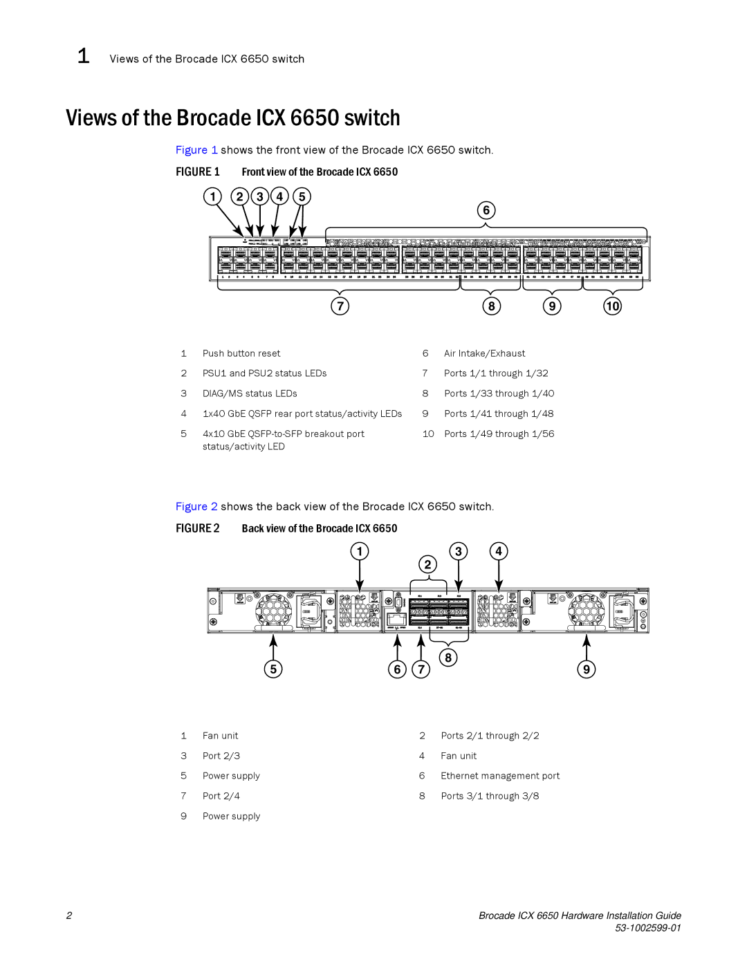
Figure 1 shows the front view of the Brocade ICX 6650 switch.
FIGURE 1 Front view of the Brocade ICX 6650
1 2 3 4 5
6
| 7 |
| 8 | 9 | 10 |
1 | Push button reset | 6 | Air Intake/Exhaust |
|
|
2 | PSU1 and PSU2 status LEDs | 7 | Ports 1/1 through 1/32 |
|
|
3 | DIAG/MS status LEDs | 8 | Ports 1/33 through 1/40 |
| |
4 | 1x40 GbE QSFP rear port status/activity LEDs | 9 | Ports 1/41 through 1/48 |
| |
5 | 4x10 GbE | 10 | Ports 1/49 through 1/56 |
| |
| status/activity LED |
|
|
|
|
Figure 2 shows the back view of the Brocade ICX 6650 switch.
FIGURE 2 Back view of the Brocade ICX 6650
1 | 3 | 4 |
2
8
5 | 6 | 7 | 9 |
1 | Fan unit | 2 | Ports 2/1 through 2/2 |
3 | Port 2/3 | 4 | Fan unit |
5 | Power supply | 6 | Ethernet management port |
7 | Port 2/4 | 8 | Ports 3/1 through 3/8 |
9 | Power supply |
|
|
2 | Brocade ICX 6650 Hardware Installation Guide |
|