580D036-072 579F180,216 580D090-150 579F240,300
FEATURES/BENEFITS
Page
Table of Contents
580D036-150 Models only
Model Number Nomenclature
Model Number Nomenclature 579F180-300 Models only
ARI* Capacity Ratings
Heating Capacities and Efficiencies Ð 580D036-150
ARI* Capacity Ratings
Heating Capacities and Efficiencies Ð 579F180-300
Rise Efficiency
Unit Size 580D
Physical Data Ð 580D036-072
Unit Size 580D Medium LOW/MEDIUM High Heat
Physical Data Ð 580D036-072
090 102 120 150 Nominal Capacity tons
Physical Data Ð 580D090-150
Quantity...Diameter Motor Hp...Rpm
Pulley Center Line Distance Std
Unit Size 580D LOW/MEDIUM High Heat Hihg Heat Medium Heat
Physical Data Ð 580D090-150
Unit Size 579F
Physical Data Ð 579F180-300
LOW/HIGH Heat
Physical Data Ð 579F180-300
Unit Size 579F
Option ACCESSORY²
Options and Accessories
Head Pressure Control
Head Pressure Control Speed Control 180,216
Time Guard II Control
Options and Accessories
Durablade Economizer
Sizes
Accusensor Control
Power Exhaust 180-300 Shown Accusensor Sensor
Only
Thermostat
Unit
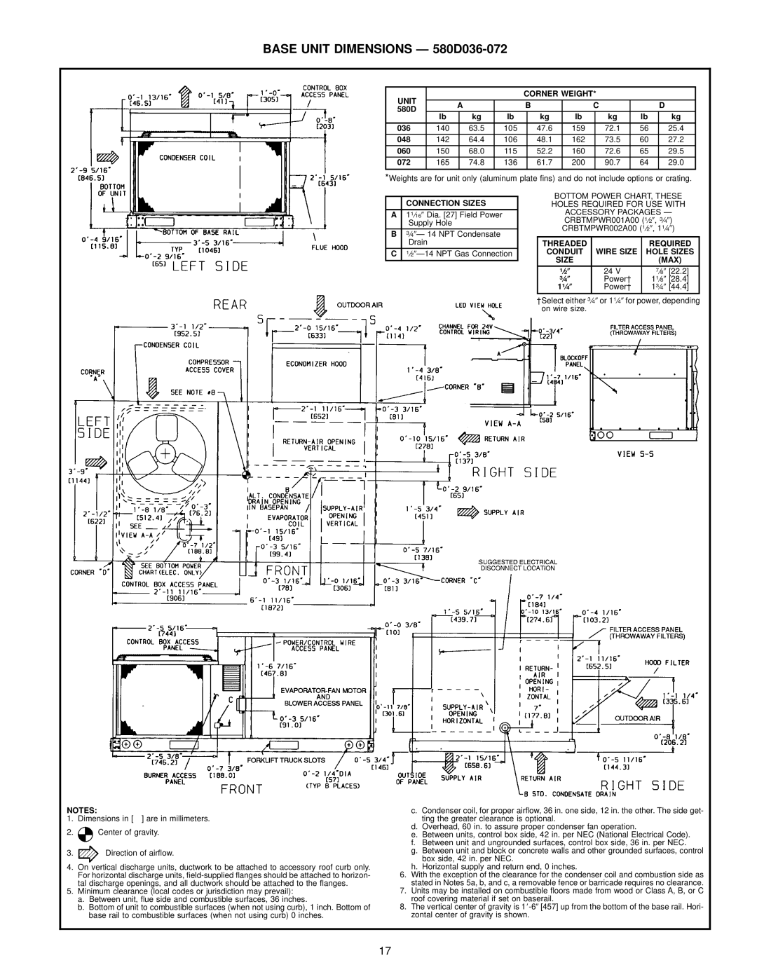
Base Unit Dimensions Ð 580D036-072
Unit Corner Weight Dimensions
Base Unit Dimensions Ð 580D090-150
486 220 636 288
Base Unit Dimensions Ð 579F180,216
Dimension
Base Unit Dimensions Ð 579F240,300
Roof Curb Ð 580D036-072
Accessory Dimensions
Roof Curb Ð 580D090-150
Accessory Dimensions
PKG. NO. REF Curb Description Height
Dimensions degrees and inches
Unit DEG
579F
Power Exhaust 579F180-300
Horizontal Supply/Return Adapter Installation 579F180-300
Accessory Curb Description Package no Height
Pre-Assembled, High Static
II Select Unit Based on Required Cooling Capacity
Selection Procedure with 579F180 example
SHC
Performance Data Cooling Capacities
Cooling Capacities
Performance Data
580D150 121¤2 Tons
Performance Data Cooling Capacities
580D120 10 Tons
4500/0.08 5250/0.10 6000/0.11 6750/0.12 7500/0.14 Condenser
579F180 15 Tons Temp F Air Entering Evaporator Ð Cfm/BF
579F216 18 Tons
5400/0.06 6000/0.07 7200/0.08 9000/0.09
7000/0.03 8750/0.05 10,000/0.07 11,250/0.09
579F240 20 Tons Temp F Air Entering Evaporator Ð Cfm/BF
579F300 25 Tons
580D036 3 Tons Ð Standard Motor Direct Drive
FAN Performance Ð 580D036-150 Vertical Discharge Units
Fiop
580D036 3 Tons Ð Alternate Motor Belt Drive
580D048 4 Tons Ð Alternate Motor Belt Drive
580D048 4 Tons Ð Standard Motor Direct Drive
580D060 5 Tons Ð Alternate Motor Belt Drive
580D060 5 Tons Ð Standard Motor Direct Drive
Rpm Bhp Watts 1800
580D072 6 Tons Air¯ow External Static Pressure in. wg
2600
1562
Rpm Bhp Watts 2250
580D090 71¤2 Tons Air¯ow External Static Pressure in. wg
2550
3100
Rpm Bhp Watts 2550
580D102 81¤2 Tons Air¯ow External Static Pressure in. wg
891 2188 3300
904 2300 3400
Rpm Bhp Watts 3000
580D120 10 Tons Air¯ow External Static Pressure in. wg
4300
985
Rpm Bhp Watts 3750
580D150 121¤2 Tons Air¯ow External Static Pressure in. wg
5100
5200
FAN Performance Ð 580D036-150 Horizontal Discharge Units
Rpm Bhp Watts 1200 569 189 641
1989 1466 2171 Bhp Brake Horsepower Input to Fan
299 761 357 859 483 901 546 943 609 1300 604 231 673
352 788 410 887 546 928 615 968 683 1400 640 284 705
1392
Medium Speed High Speed 208 230, 460, 575 230,460, 575
1365 2038 1426
1331 1986 1400 2227 1461
1514
1536
1496 2240 1529
1603
894
997 3055 1040 3333 Bhp Brake Horsepower Input to Fan
882
895
Rpm Bhp Watts 2550 669 627 867 692 1056 754
1062 3676 1102 3860 Bhp Brake Horsepower Input to Fan
783
812
1008
962
973
1019
1166
Bhp Watts 3750
1178
1131
FAN Performance Ð 579F180-300 Units
Performance Data FAN Performance Ð 579F180-300 Units
579F240 20 Tons Air¯ow External Static Pressure in. wg
10,000 Bhp Brake Horsepower Input to Fan
Rpm Bhp Watts 6000
9500
579F300 25 Tons Air¯ow
10,500 11,000 11,250 Bhp Brake Horsepower Input to Fan
Rpm Bhp Watts 500
3507
Sound Weighted Octave Bands Unit Rating
Sound Power Total Unit
AIR Quantity Limits
Unit Minimum CFM Maximum CFM
ACCESSORY/FIOP Static PRESSURE* in. wg − 579F180-300
ACCESSORY/FIOP Static PRESSURE* in. wg − 580D090-150
Component CFM
Unit Motor Pulley Turns Open
Btuh Nominal
Altitude COMPENSATION* Ð
Nominal Input
Input
Altitude COMPENSATION* Ð 580D090-150
Fan Performance Using Accessory Power Exhaust 579F180-300
EVAPORATOR-FAN Motor Efficiency
Altitude Derating FACTOR* Ð ALL Units
Maximum Unit EVAPORATOR-FAN Acceptable
EVAPORATOR-FAN Motor Performance
Continuous Operating AMP Draw BHP
580D036
RLA LRA FLA MCA MOCP²
Electrical Data Ð 580D036-150
Electrical Data Ð 579F180-300
Vertical Discharge Ducting
Typical Piping and Wiring Ð 580D036-150
Horizontal Discharge Ducting
NEC Ð National Electrical Code
579F180 shown
Typical Piping and Wiring Ð 579F180-300
Typical Wiring Schematic Ð 580D036-150
Typical Wiring Schematic 579F240-300, 460-v shown
PRI
AHA
IDM
IFC
Operating Sequence
Controls
Cooling, Units With Parablade Economizer 580D036-072
Controls
580D036-150
Application Data
Application Data
Part 1 Ð General
Guide Specifications Ð 580D036-150
Guide Specifications Ð 580D036-150
Guide Specifications Ð 580D036-150
Guide Specifications Ð 579F180-300
Guide Specifications Ð 579F180-300
Copyright 1998 Bryant Heating & Cooling Systems