Cabletron Systems EMM-E6 manual Reset Cpu D C B A Stby Rcv Xmt Cln, Lanview Leds

Models: EMM-E6

1 64
Download 64 pages 974 b
Page 18
Image 18
2.3LANVIEW LEDS

Chapter 2: Controls and Indicators

2.3LANVIEW LEDS

The LANVIEW LEDs on the EMM-E6 faceplate provide diagnostic and status monitoring information. The LEDs are identified by labels which border the LED in question.

RESET RESET

CPU Manual background

D C B A

STBY Manual background

RCV Manual background

XMT Manual background

CLN Manual background

1926n04

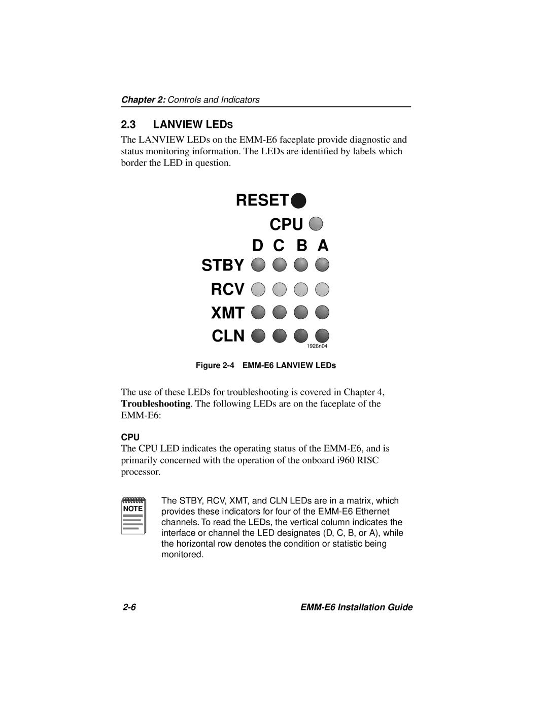
Figure 2-4 EMM-E6 LANVIEW LEDs

The use of these LEDs for troubleshooting is covered in Chapter 4, Troubleshooting. The following LEDs are on the faceplate of the EMM-E6:

CPU

The CPU LED indicates the operating status of the EMM-E6, and is primarily concerned with the operation of the onboard i960 RISC processor.

NOTE

The STBY, RCV, XMT, and CLN LEDs are in a matrix, which provides these indicators for four of the EMM-E6 Ethernet channels. To read the LEDs, the vertical column indicates the interface or channel the LED designates (D, C, B, or A), while the horizontal row denotes the condition or statistic being monitored.

2-6

EMM-E6 Installation Guide

Page 18
Image 18
Cabletron Systems EMM-E6 manual Reset Cpu D C B A Stby Rcv Xmt Cln, Lanview Leds