CHAPTER 2
CONTROLS AND INDICATORS
This chapter identifies and describes the components and operational indicators of the
2.1THE FACEPLATE
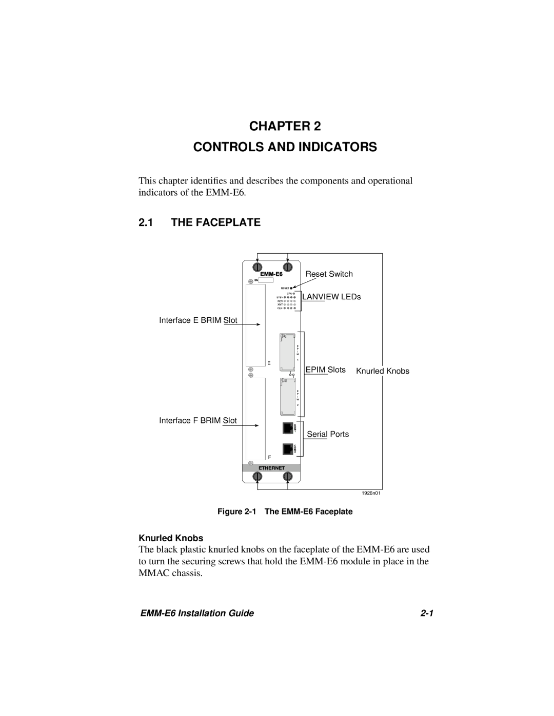
Interface E BRIM Slot
Interface F BRIM Slot
E
F
Reset Switch
LANVIEW LEDs
EPIM Slots Knurled Knobs
Serial Ports
1926n01
Figure 2-1 The EMM-E6 Faceplate
Knurled Knobs
The black plastic knurled knobs on the faceplate of the
|