Chapter 3: Installation
1926n10
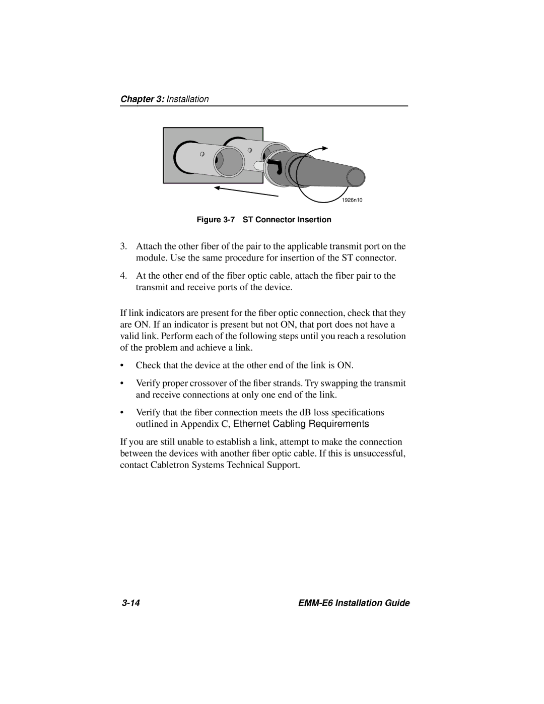
Figure 3-7 ST Connector Insertion
3.Attach the other fiber of the pair to the applicable transmit port on the module. Use the same procedure for insertion of the ST connector.
4.At the other end of the fiber optic cable, attach the fiber pair to the transmit and receive ports of the device.
If link indicators are present for the fiber optic connection, check that they are ON. If an indicator is present but not ON, that port does not have a valid link. Perform each of the following steps until you reach a resolution of the problem and achieve a link.
•Check that the device at the other end of the link is ON.
•Verify proper crossover of the fiber strands. Try swapping the transmit and receive connections at only one end of the link.
•Verify that the fiber connection meets the dB loss specifications outlined in Appendix C, Ethernet Cabling Requirements.
If you are still unable to establish a link, attempt to make the connection between the devices with another fiber optic cable. If this is unsuccessful, contact Cabletron Systems Technical Support.
|