Chapter 3: Installation
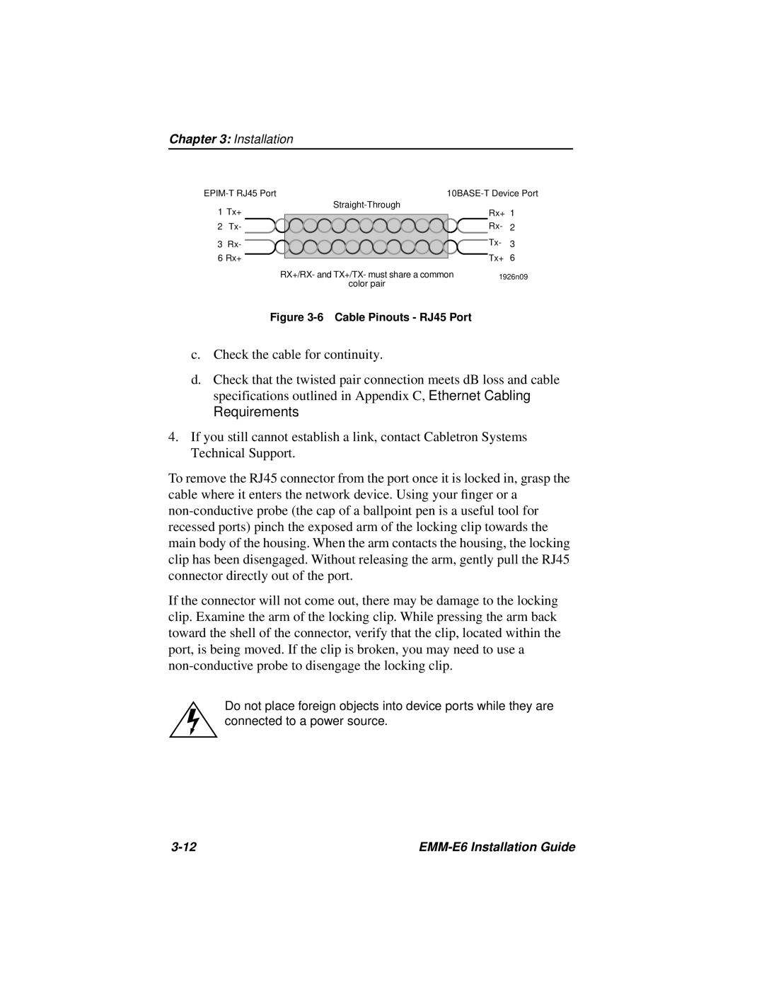
1 Tx+ | Rx+ 1 | |||
| ||||
2 | Tx- |
| Rx- | 2 |
3 | Rx- |
| Tx- | 3 |
6 Rx+ |
| Tx+ | 6 | |
|
| RX+/RX- and TX+/TX- must share a common | 1926n09 | |
|
| color pair |
|
|
Figure 3-6 Cable Pinouts - RJ45 Port
c.Check the cable for continuity.
d.Check that the twisted pair connection meets dB loss and cable specifications outlined in Appendix C, Ethernet Cabling Requirements.
4.If you still cannot establish a link, contact Cabletron Systems Technical Support.
To remove the RJ45 connector from the port once it is locked in, grasp the cable where it enters the network device. Using your finger or a
If the connector will not come out, there may be damage to the locking clip. Examine the arm of the locking clip. While pressing the arm back toward the shell of the connector, verify that the clip, located within the port, is being moved. If the clip is broken, you may need to use a
Do not place foreign objects into device ports while they are connected to a power source.
|