Installation
RESET 
CPU 
D C B A
STBY 
RCV 
XMT 
CLN 
1926n04
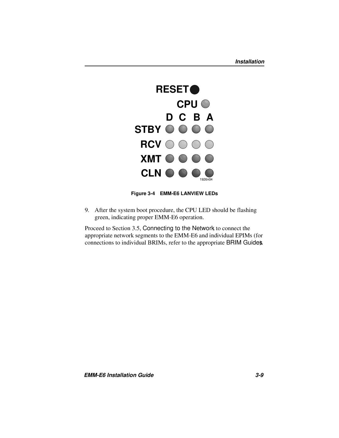
Figure 3-4 EMM-E6 LANVIEW LEDs
9.After the system boot procedure, the CPU LED should be flashing green, indicating proper
Proceed to Section 3.5, Connecting to the Network, to connect the appropriate network segments to the
|