APPENDIX B

UPGRADING THE EMM-E6

This appendix describes how to incorporate additional or expanded capabilities into the EMM-E6. This appendix describes the procedures for the addition of a BRIM or EPIM module and the addition of Single In-line Memory Modules (SIMMs).

B.1 LOCATING BRIM CONNECTORS

This section points out Bridge Router Interface Module (BRIM) connector locations on your EMM-E6 board. Refer to your BRIM Guide for specific installation procedures and additional information.

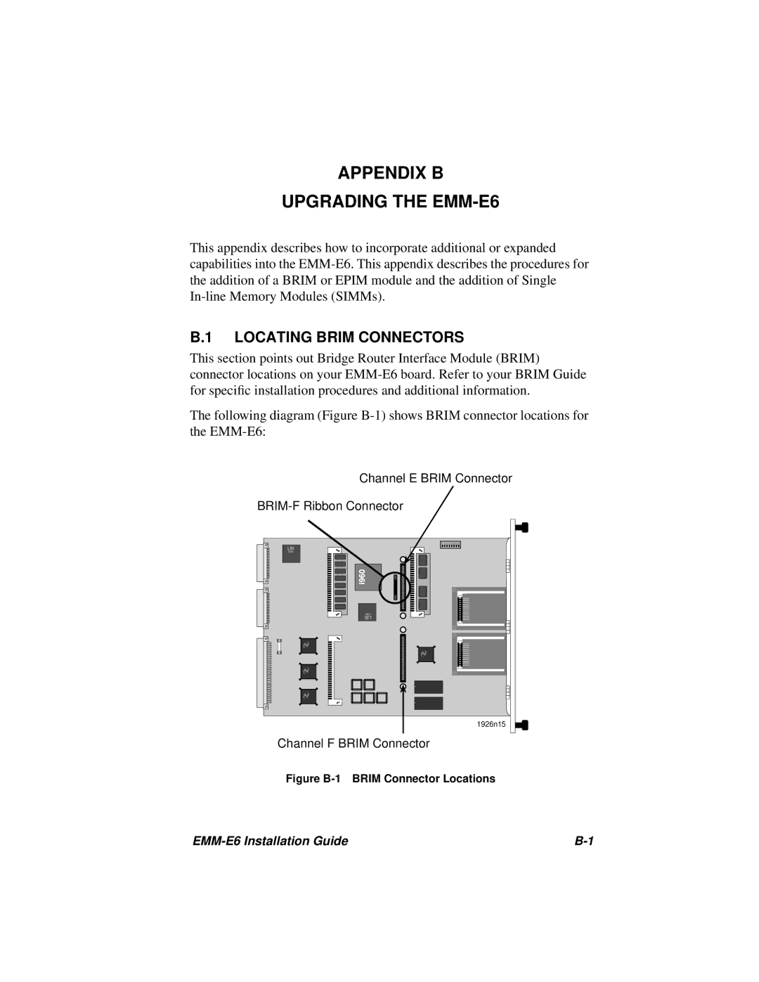
The following diagram (Figure B-1) shows BRIM connector locations for the EMM-E6:

Channel E BRIM Connector

BRIM-F Ribbon Connector

LSI

Logic

Logic

LSI

1926n15

Channel F BRIM Connector

Figure B-1 BRIM Connector Locations

EMM-E6 Installation Guide

B-1

Page 51
Image 51
Cabletron Systems manual Appendix B Upgrading the EMM-E6, Locating Brim Connectors