SmartSwitch Router User Reference Manual
9032578-04
SmartSwitch Router User Reference Manual
Industry Canada Notice
Vcci Notice
Cabletron SYSTEMS, INC Program License Agreement
SmartSwitch Router User Reference Manual
SmartSwitch Router User Reference Manual
SmartSwitch Router User Reference Manual
Cabletron Systems Limited Program License Agreement
SmartSwitch Router User Reference Manual
Safety Information
Laser Radiation and Connectors
EC Directive 89/336/EEC
EC Directive 73/23/EEC
SmartSwitch Router User Reference Manual
Contents
Hot Swapping Line Cards and Control Modules
SmartTRUNK Configuration Guide
Creating a non-IP/non-IPX Vlan
Vrrp Configuration Guide
127
Multicast Routing Configuration Guide 199
IP Multicast Overview 199
209
Web Hosting Configuration Guide 233
255
QoS Configuration Guide 283
WAN Configuration Guide 315
Contents
About This Manual
How to Use This Manual
Preface
Who Should Read This Manual?
Preface
Related Documentation
Installing and setting up the SSR
Managing the SSR using Cabletron’s
For Information About See
Preface SmartSwitch Router User Reference Manual
Chapter SSR Product Overview
SSR Hardware and software specifications
Feature Specification
IPX RIP, SAP
Multicast IGMP, Dvmrp
Supported Media Encapsulation Type
Supported Routing Protocols
Routing Information Protocol RIP Version 1
Configuring the SmartSwitch Router
Understanding the Command Line Interface
Common CLI key commands
Basic Line Editing Commands
Access Modes
Key Sequence Command
User Mode
Enable Mode
Exit
Configure Mode
Boot Prom Mode
Pvst
Boot and System Image
Loading System Images and Configuration Files
Disabling a Function or Feature
Configuration Files
Loading System Image Software
Ssr# system show version
Enter the system image list command to verify the change
Loading Boot Prom Software
Activating the Configuration Commands in the Scratchpad
Enter yes or y to activate the changes
Copying the Configuration to the Startup Configuration File
CLI displays the following message
Displaying Configuration Changes
Managing the SSR
Configuring NTP
Setting the SSR Name
Setting SSR Date and Time
Configuring DNS
Configuring the SSR CLI
Configuring Snmp Services
Connecting Between the SSR and Other Systems
Configuring Logging
Monitoring Configuration
Task Command
Show the configuration changes
Show the SSR login banner
Show the type of Power-On Self Test Post
Reboot Show the status of the switching fabric
Hot Swapping Line Cards
Chapter Hot Swapping Line Cards Control Modules
Hot Swapping Overview
Deactivating the Line Card
Removing the Line Card
Hot Swapping One Type of Line Card With Another
Installing a New Line Card
Hot Swapping a Secondary Control Module
Deactivating the Control Module
Removing the Control Module
Hot Swapping a Switching Fabric Module SSR 8600 only
Installing the Control Module
SSR-SF-16 Offline Switching Fabric
Spanning Tree Ieee 802.1d
Chapter Bridging Configuration Guide
Bridging Overview
Vlan Overview
Bridging Modes Flow-Based and Address-Based
Protocol-based VLANs
Port-based VLANs
MAC-address-based VLANs
Subnet-based VLANs
Policy-based VLANs
SSR Vlan Support
Multicast-based VLANs
VLANs and the SSR
Access Ports and Trunk Ports 802.1Q support
Ports, VLANs, and L3 Interfaces
Explicit and Implicit VLANs
Configuring SSR Bridging Functions
Configuring Address-based or Flow-based Bridging
Configuring Spanning Tree
Address-Based Bridge Table Flow-Based Bridge Table
More ports for a particular Vlan
Adjusting Spanning-Tree Parameters
Setting the Bridge Priority
Assigning Port Costs
Setting a Port Priority
Adjusting Bridge Protocol Data Unit Bpdu Intervals
Defining the Maximum Age
Adjusting the Interval between Hello Times
Defining the Forward Delay Interval
Configuring VLANs for Bridging
Configuring a Port or Protocol based Vlan
Configuring Vlan Trunk Ports
Creating a Port or Protocol Based Vlan
Configuring Layer-2 Filters
Monitoring Bridging
Creating a non-IP/non-IPX Vlan
Configuration Examples
Creating an IP or IPX Vlan
Show information on MACs
Page
Chapter SmartTRUNK Configuration Guide
Overview
Add Physical Ports to the SmartTRUNK
Configuring SmartTRUNKs
Creating a SmartTRUNK
Monitoring SmartTRUNKs
Specify Traffic Distribution Policy Optional
Example Configurations
St.2 St.4 Router Switch Server
SmartTRUNK Configuration Guide
Page
Dhcp Overview
Configuration Guide
Chapter
Configuring Client Parameters
Configuring Dhcp
Configuring an IP Address Pool
Client Parameters
Configuring a Static IP Address
Grouping Scopes with a Common Interface
Monitoring the Dhcp Server
Configuring Dhcp Server Parameters
Updating the Lease Database
Define an IP address pool for addresses 10.1.1.10 through
Dhcp Configuration Examples
Define Dhcp network parameters for the scope ‘scope1’
Define a static IP address for
Configuring Secondary Subnets
Secondary Subnets and Directly-Connected Clients
Include ‘scope2’ in the superscope ‘super1’
Interacting with Relay Agents
Define the address pool for ‘scope1’
Page
Chapter IP Routing Configuration Guide
IP Routing Overview
Unicast Routing Protocols
IP Routing Protocols
SSR supports standards-based TCP, UDP, and IP
Multicast Routing Protocols
Configuring IP Interfaces for a Vlan
Configuring IP Interfaces and Parameters
Configuring IP Addresses to Ports
Specifying Ethernet Encapsulation Method
Configuring Proxy ARP
Configuring Address Resolution Protocol ARP
Configuring ARP Cache Entries
Defining MAC-to-IP Address Mappings
Configuring Reverse Address Resolution Protocol Rarp
Specifying IP Interfaces for Rarp
Monitoring Rarp
Configuring DNS Parameters
Configuring IP Services Icmp
Specify ping
Configuring Denial of Service DOS
Configuring IP Helper
Configuring Direct Broadcast
Configuring Router Discovery
Monitoring IP Parameters
Assigning IP/IPX Interfaces
IP Routing Configuration Guide
Configuring Vrrp
Vrrp Overview
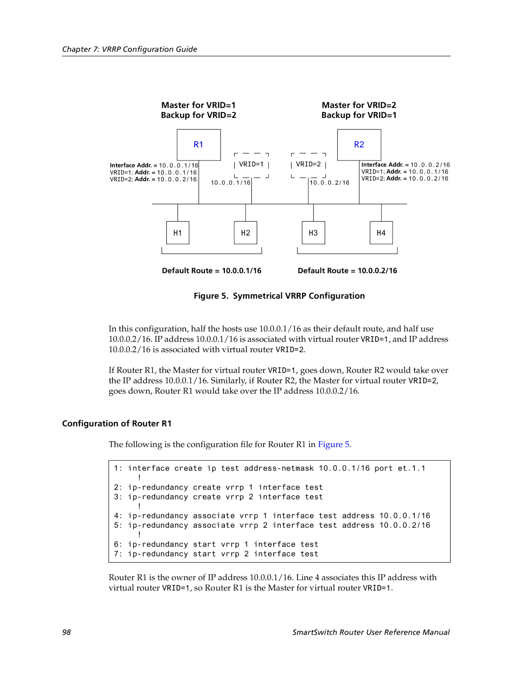
Configuration of Router R1
Basic Vrrp Configuration
Backup
Following is the configuration file for Router R1 in Figure
Following is the configuration file for Router R2 in Figure
Symmetrical Configuration
Configuration for Router R2
Master for VRID=1 Master for VRID=2 Backup for VRID=2
Symmetrical Vrrp Configuration
Multi-Backup Configuration
Configuration of Router R2
Multi-Backup Vrrp Configuration
SmartSwitch Router User Reference Manual 101
Virtual Router Default Priority Configured Priority
Following is the configuration file for Router R3 in Figure
Additional Configuration
Configuration of Router R3
Setting Pre-empt Mode
Setting the Backup Priority
Setting the Advertisement Interval
Ip-redundancy trace
Setting an Authentication Key
Monitoring Vrrp
Virtual routers Display information about all
Vrrp Configuration Notes
Ip-redundancy show
Specific virtual router
SmartSwitch Router User Reference Manual 107
108
RIP Overview
Chapter RIP Configuration Guide
Configuring RIP
Enabling and Disabling RIP
Configuring RIP Interfaces
Configuring RIP Parameters
To RIP
Set the authentication method
Characters Set the authentication method
Specify that RIP V2 packets
Monitoring RIP
Configuring RIP Route Preference
Configuring RIP Route Default-Metric
Configuration Example
114
Ospf
Ospf Overview
Disable Ospf
Configuring Ospf
Enable Ospf
Ospf Multipath
Ospf Interface Parameters
Configuring Ospf Interface Parameters
Ospf Parameter Default Value
Add an interface to an Ospf area
Configuring an Ospf Area
Create an Ospf area
Add a stub host to an Ospf area
Configuring Ospf Area Parameters
Creating Virtual Links
Add a network to an Ospf area for
Link
Configuring Ospf over Non-Broadcast Multiple Access
Create a virtual
Set virtual link
Monitoring Ospf
Ospf Configuration Examples
Exporting All Interface & Static Routes to Ospf
Exporting All RIP, Interface & Static Routes to Ospf
Create a RIP export source
Create a Ospf export destination for type-1 routes
Create a Ospf export destination for type-2 routes
Create a Static export source
Create OSPF-ASE export source
Create a RIP export destination
Create Ospf export source
R10
Chapter BGP Configuration Guide
BGP Overview
Basic BGP Tasks
SSR BGP Implementation
Configuring a BGP Peer Group
Setting the Autonomous System Number
Setting the Router ID
Ip-router global set autonomous-system num1 loops num2
Where
Autonomous-system number
Starting BGP
Using AS-Path Regular Expressions
Adding and Removing a BGP Peer
132
To import MCI routes with a preference
Using the AS Path Prepend Feature
AS-Path Regular Expression Examples
BGP Configuration Examples
Following is an example
BGP Peering Session Example
Physical Link Peering Relationship
CLI configuration for router SSR1 is as follows
AS-1 AS-2
Gated.conf file for router SSR1 is as follows
Ibgp Configuration Example
CLI configuration for router SSR2 is as follows
Gated.conf file for router SSR2 is as follows
Ibgp Routing Group Example
Sample Ibgp Configuration Routing Group Type
AS-64801
Following lines in the Cisco router configure Ospf
Ibgp Internal Group Example
Illustrates a sample Ibgp Internal group configuration
Sample Ibgp Configuration Internal Group Type
SmartSwitch Router User Reference Manual 143
Configuration for router C2 a Cisco router is as follows
Ebgp Multihop Configuration Example
Configuration for router C1 a Cisco router is as follows
AS-64800
Physical Link
CLI configuration for router SSR3 is as follows
Gated.conf file for router SSR3 is as follows
CLI configuration for router SSR4 is as follows
Community Attribute Example
Gated.conf file for router SSR4 is as follows
Sample BGP Configuration Specific Community
Sample BGP Configuration Well-Known Community
, router SSR11 has the following configuration
, router SSR13 has the following configuration
, router SSR10 has the following configuration
, router SSR14 has the following configuration
SmartSwitch Router User Reference Manual 153
LocalPref Attribute Example
Sample BGP Configuration LocalPref Attribute
Multi-Exit Discriminator Attribute Example
Sample BGP Configuration MED Attribute
Router SSR6 has the following CLI configuration
AS-64900
Router SSR8 has the following CLI configuration
Ebgp Aggregation Example
AS-64901
Router SSR9 has the following CLI configuration
Route Reflection Example
Shows a sample configuration that uses route reflection
AS-64902
SmartSwitch Router User Reference Manual 161
162
Chapter Routing Policy Configuration Guide
Route Import and Export Policy Overview
Preference
Default Preference Values
Preference Defined by CLI Command Default
Import Policies
Import-Source
Export-Destination
Export Policies
Route-Filter
Export-Source
Specifying a Route Filter
Aggregates and Generates
Aggregate-Destination
Aggregate-Source
Authentication
Authentication Methods
Configuring Simple Routing Policies
Authentication Keys and Key Management
Redistributing Static Routes
Redistributing Directly Attached Networks
Redistributing Aggregate Routes
Redistributing RIP into RIP
Redistributing RIP into Ospf Redistributing Ospf to RIP
Routes into Ospf
Simple Route Redistribution Examples
To redistribute aggregate
Example 1 Redistribution into RIP
Example 2 Redistribution into Ospf
Exporting a Given Static Route to All RIP Interfaces
Exporting All Static Routes to All RIP Interfaces
176
Configuring Advanced Routing Policies
178
Creating an Export Destination
Creating an Export Source
Creating an Aggregate Route
Creating an Import Source
Creating a Route Filter
Create a RIP import
SmartSwitch Router User Reference Manual 181
Examples of Import Policies
Creating an Aggregate Destination
Creating an Aggregate Source
Example 1 Importing from RIP
R41
184
Example 2 Importing from Ospf
186
R41
Importing a Selected Subset of OSPF-ASE Routes
Examples of Export Policies
Example 1 Exporting to RIP
Ip-router policy create rip-export-source ripExpSrc
Exporting a Given Static Route to a Specific RIP Interface
Exporting Aggregate-Routes into RIP
Ip-router policy create aggr-export-source aggrExpSrc
Example 2 Exporting to Ospf
SmartSwitch Router User Reference Manual 195
196
SmartSwitch Router User Reference Manual 197
198
Igmp Overview
Chapter Multicast Routing Configuration Guide
IP Multicast Overview
Dvmrp Overview
Configuring Igmp Query Interval
Configuring Igmp
Configuring Igmp on an IP Interface
Configuring Igmp Response Wait Time
Starting and Stopping Dvmrp
Configuring Dvmrp
Configuring Per-Interface Control of Igmp Membership
Configuring the Dvmrp Routing Metric
Configuring Dvmrp on an Interface
Configuring Dvmrp Parameters
Configuring Dvmrp TTL & Scope
Configuring a Dvmrp Tunnel
Monitoring Igmp & Dvmrp
Show all multicast routes
Show all interfaces running
Multicast protocols Igmp
Page
208
Chapter IP Policy-Based Forwarding Configuration Guide
Associating the Profile with an IP Policy
Configuring IP Policies
Defining an ACL Profile
Creating Multi-statement IP Policies
Setting Load Distribution for Next-hop Gateways
Setting the IP Policy Action
Applying an IP Policy to an Interface
Checking the Availability of Next-hop Gateways
An IP interface Apply a defined IP policy to
IP Policy Configuration Examples
Routing Traffic to Different ISPs
All IP interfaces on the SSR
Using an IP policy to route traffic to two different ISPs
Prioritizing Service to Customers
Using an IP policy to prioritize service to customers
Authenticating Users through a Firewall
Using an IP policy to authenticate users through a firewall
Firewall Load Balancing
Selecting Next Hop Gateway from IP Packet Information
IP policies
Monitoring IP Policies
Display information about all
Display statistics about a
Ip-policy show interface interface
SmartSwitch Router User Reference Manual 221
222
Chapter Network Address Translation Configuration Guide
Configuring NAT
Setting Inside and Outside Interfaces
Static
Setting NAT Rules
Managing Dynamic Bindings
Dynamic
NAT and FTP
Static Configuration
Specify the FTP session timeout
Monitoring NAT
Next, define the interfaces to be NAT inside or outside
Using Static NAT
First step is to create the interfaces
Then, define the NAT static rules
Dynamic Configuration
Using Dynamic NAT
Dynamic NAT with IP Overload PAT Configuration
Using Dynamic NAT with IP Overload
Dynamic NAT with Outside Interface Redundancy
Using Dynamic NAT with Matching Interface Redundancy
232
Chapter Web Hosting Configuration Guide
Creating the Server Group
Configuring Load Balancing
Load Balancing
Specifying Load Balancing Policy Optional
Setting Server Status
Adding Servers to the Load Balancing Group
Load Balancing and FTP
Allowing Access to Load Balancing Servers
Setting Timeouts for Load Balancing Mappings
Configuration Examples
Displaying Load Balancing Information
Ftp.quick.com Internet Router User Queries
207.135.89.16 10.1.1.1 Ftp.quick..com 10.1.1.2
Virtual IP Address Ranges
207.135.89.16 207.135.89.17 207.135.89.18
Configuring Web Caching
Web Caching
Redirected to cache servers
Creating the Cache Group
Specifying the Clients for the Cache Group Optional
Not redirected to cache servers
Bypassing Cache Servers
Configuration Example
Other Configurations
Proxy Server Redundancy
Distributing Frequently-Accessed Sites Across Cache Servers
Monitoring Web-Caching
Show caching policy information
Show cache server information
RIP Routing Information Protocol
Chapter IPX Routing Configuration Guide
IPX Routing Overview
SAP Service Advertising Protocol
IPX Addresses
Configuring IPX RIP & SAP
Creating IPX Interfaces
Configuring IPX Interfaces for a Vlan
Configuring IPX Interfaces and Parameters
Configuring IPX Addresses to Ports
Specifying IPX Encapsulation Method
Enabling IPX RIP
Configuring IPX Routing
Configuring Static Routes
Enabling SAP
Creating an IPX Access Control List
Configuring Static SAP Table Entries
Controlling Access to IPX Networks
Creating an IPX GNS Access Control List
Creating an IPX Type 20 Access Control List
Creating an IPX SAP Access Control List
Creating an IPX RIP Access Control List
Monitoring an IPX Network
Adds a SAP access list Adds a GNS access list
254
Chapter Access Control List Configuration Guide
ACL Basics
Defining Selection Criteria in ACL Rules
How ACL Rules are Evaluated
Implicit Deny Rule
Allowing External Responses to Established TCP Connections
Editing ACLs Offline
Following ACL illustrates this feature
Creating and Modifying ACLs
Maintaining ACLs Using the ACL Editor
These uses of ACLs are described in the following sections
Using ACLs
Applying ACLs to Interfaces
Applying ACLs to Services
Using ACLs as Profiles
Using Profile ACLs with the IP Policy Facility
Following SSR features use ACL profiles
SSR Feature ACL Profile Usage
Using Profile ACLs with the Traffic Rate Limiting Facility
Using Profile ACLs with Dynamic NAT
Using Profile ACLs with the Port Mirroring Facility
Using Profile ACLs with the Web Caching Facility
Redirecting Http Traffic to Cache Servers
Enabling ACL Logging
Preventing Web Objects From Being Cached
Monitoring ACLs
270
Chapter Security Configuration Guide
Security Overview
Configuring SSR Access Security
Configuring Radius
Monitoring Tacacs
Configuring Tacacs
Monitoring Radius
Configuring Tacacs Plus
Monitoring Tacacs Plus
Configuring Passwords
Layer-2 Security Filters
Configuring Layer-2 Address Filters
Configuring Layer-2 Port-to-Address Lock Filters
Configure a source static
Configuring Layer-2 Static Entry Filters
Configuring Layer-2 Secure Port Filters
Configure a destination static
Monitoring Layer-2 Security Filters
Static Entries Example
Layer-2 Filter Examples
Et.1.1 Et.1.2 Et.1.3 Hub
Port-to-Address Lock Examples
Example 2 Secure Ports
Layer-3 Access Control Lists ACLs
282
Chapter QoS Configuration Guide
QoS & Layer-2/Layer-3/Layer-4 Flow Overview
Layer-2 and Layer-3 & Layer-4 Flow Specification
Precedence for Layer-3 Flows
SSR Queuing Policies
Configuring Layer-2 QoS
Traffic Prioritization for Layer-2 Flows
Configuring IP QoS Policies
Traffic Prioritization for Layer-3 & Layer-4 Flows
Setting an IPX QoS Policy
Configuring IPX QoS Policies
Setting an IP QoS Policy
Specifying Precedence for an IP QoS Policy
ToS Rewrite
Configuring SSR Queueing Policy
Allocating Bandwidth for a Weighted-Fair Queuing Policy
Specifying Precedence for an IPX QoS Policy
Configuring ToS Rewrite for IP Packets
MBZ
Tos-rewrite
Show all IP QoS flows
Monitoring QoS
Limiting Traffic Rate
Show all IPX QoS flows
Apply a rate limit profile to an
Example Configuration
Define a rate limit profile
Interface
Displaying Rate Limit Information
Interface interface
294
Chapter Performance Monitoring Guide
Performance Monitoring Overview
MAC table Show information about a
Show port error statistics
Show information about the master
Particular MAC address Show info about multicasts
Only IP ACLs can be specified for port mirroring
Configuring the SSR for Port Mirroring
Monitoring Broadcast Traffic
298
Configuring and Enabling Rmon
Rmon Overview
Example of Rmon Configuration Commands
Rmon Groups
Lite Rmon Groups
Standard Rmon Groups
Professional Rmon Groups
Control Tables
Using Rmon
Configuring Rmon Groups
String status enabledisable
Enabledisable
Num status enabledisable
Size owner string status enabledisable
Rmon protocol-distribution index index-number
Port port owner string status enabledisable
Oid type absolutedelta status enabledisable
Rmon user-history-control index index-number
Displaying Rmon Information
Rmon CLI Filters
Following shows Host table output without a CLI filter
01000CCCCCCC
Creating Rmon CLI Filters
Troubleshooting Rmon
Using Rmon CLI Filters
312
Allocating Memory to Rmon
Ssr# rmon show status Rmon Status
Rmon set memory number
WAN
WAN Overview
Static, Mapped, and Dynamic Peer IP/IPX Addresses
Configuring WAN Interfaces
Primary and Secondary Addresses
Static Addresses
Mapped Addresses
Following command line displays an example for a Vlan
Following command line displays two examples for PPP
Dynamic Addresses
Packet Compression
Following command line displays an example for PPP
Forcing Bridged Encapsulation
Nature of the Data
Example Configurations
Average Packet Size
Link Integrity
WAN Quality of Service
Packet Encryption
Congestion Management
Weighted-Fair Queueing
Source Filtering and ACLs
Random Early Discard RED
Adaptive Shaping
Frame Relay Overview
Virtual Circuits
Configuring Frame Relay Interfaces for the SSR
Permanent Virtual Circuits PVCs
Setting up a Frame Relay Service Profile
Applying a Service Profile to an Active Frame Relay WAN Port
Frame Relay Port Configuration
Monitoring Frame Relay WAN Ports
326
Use of LCP Magic Numbers
Configuring PPP Interfaces
Point-to-Point Protocol PPP Overview
Setting up a PPP Service Profile
Defining the Type and Location of a PPP Interface
Compression on MLP Bundles or Links
Applying a Service Profile to an Active PPP Port
Configuring Multilink PPP Bundles
PPP Port Configuration
Monitoring PPP WAN Ports
Ssrconfig# ppp apply service profile2 ports hs.5.1
WAN Configuration Examples
Simple Configuration File
Multi-Router WAN Configuration
Multi-router WAN configuration
Router R2 Configuration File
Router R1 Configuration File
Following configuration file applies to Router R1
Following configuration file applies to Router R2
Router R4 Configuration File
Router R3 Configuration File
Following configuration file applies to Router R3
Following configuration file applies to Router R4
Router R6 Configuration File
Router R5 Configuration File
Following configuration file applies to Router R5
Following configuration file applies to Router R6
SmartSwitch Router User Reference Manual 337
338