A
BINDER SIDE
B
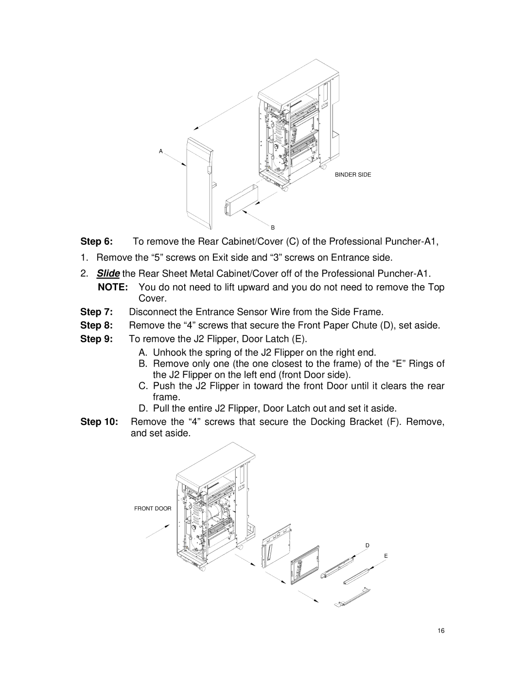
Step 6: To remove the Rear Cabinet/Cover (C) of the Professional
1.Remove the “5” screws on Exit side and “3” screws on Entrance side.
2.Slide the Rear Sheet Metal Cabinet/Cover off of the Professional
NOTE: You do not need to lift upward and you do not need to remove the Top Cover.
Step 7: Disconnect the Entrance Sensor Wire from the Side Frame.
Step 8: Remove the “4” screws that secure the Front Paper Chute (D), set aside.
Step 9: To remove the J2 Flipper, Door Latch (E).
A.Unhook the spring of the J2 Flipper on the right end.
B.Remove only one (the one closest to the frame) of the “E” Rings of the J2 Flipper on the left end (front Door side).
C.Push the J2 Flipper in toward the front Door until it clears the rear frame.
D.Pull the entire J2 Flipper, Door Latch out and set it aside.
Step 10: Remove the “4” screws that secure the Docking Bracket (F). Remove, and set aside.
FRONT DOOR
D
E
16