NOTE: Once you remove the screws that secure the rear cover, it will slide out from under the top cover. You do not need to remove the top cover.
Step 3: Remove the two screws holding the Die rail at the front of the Professional
Step 4: Remove the four screws holding the Die rail at the rear of the Professional
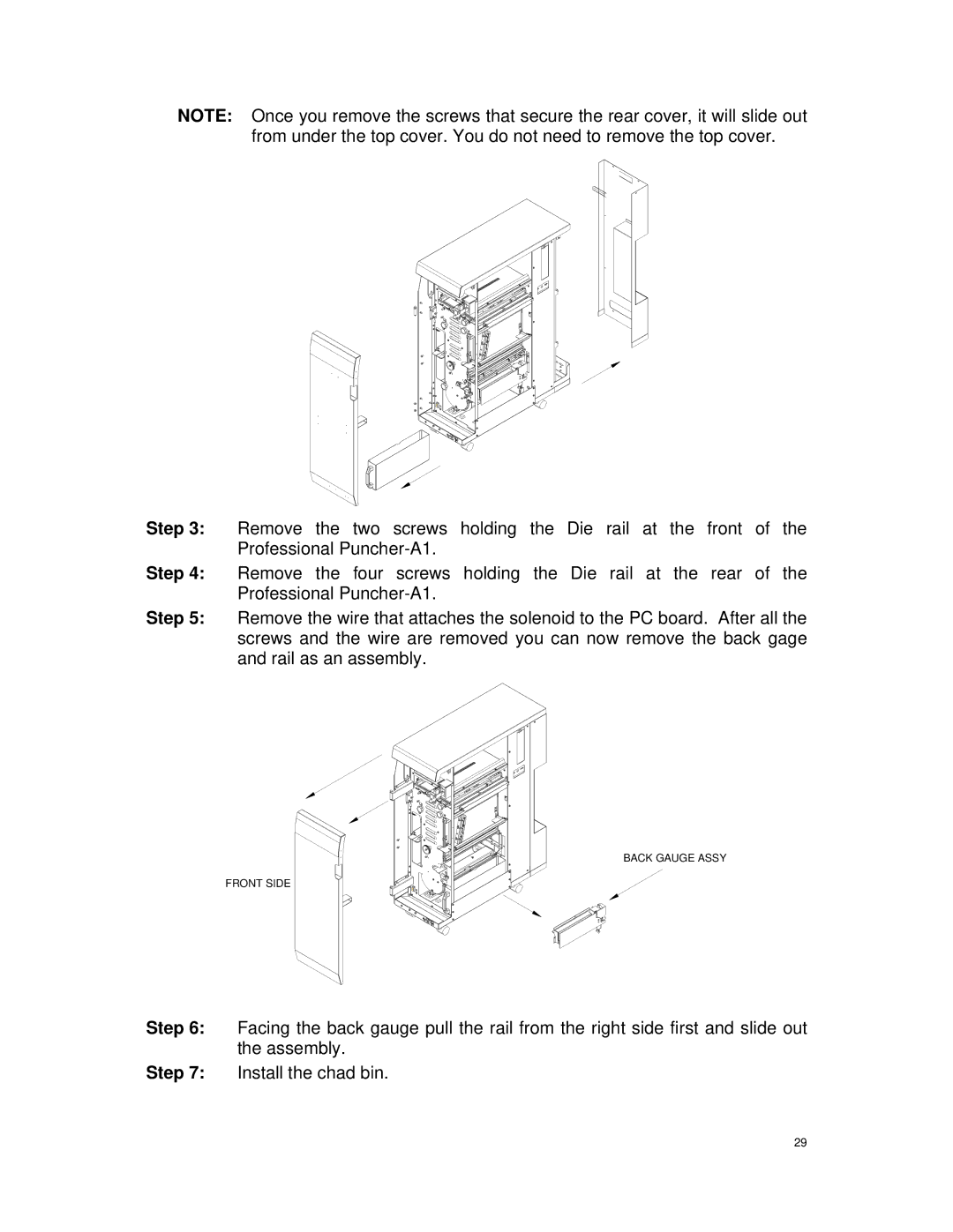
Step 5: Remove the wire that attaches the solenoid to the PC board. After all the screws and the wire are removed you can now remove the back gage and rail as an assembly.
BACK GAUGE ASSY
FRONT SIDE
Step 6: Facing the back gauge pull the rail from the right side first and slide out the assembly.
Step 7: Install the chad bin.
29