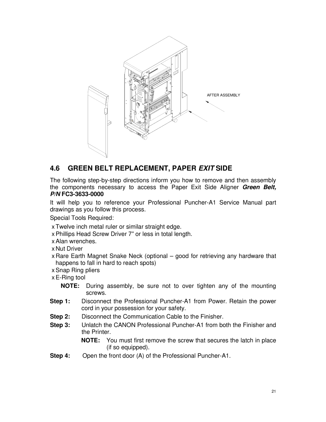
AFTER ASSEMBLY
4.6GREEN BELT REPLACEMENT, PAPER EXIT SIDE
The following
P/N FC3-3633-0000
It will help you to reference your Professional
Special Tools Required:
•Twelve inch metal ruler or similar straight edge.
•Phillips Head Screw Driver 7” or less in total length.
•Alan wrenches.
•Nut Driver
•Rare Earth Magnet Snake Neck (optional – good for retrieving any hardware that happens to fall in hard to reach spots)
•Snap Ring pliers
•
NOTE: During assembly, be sure not to over tighten any of the mounting screws.
Step 1: Disconnect the Professional
Step 2: Disconnect the Communication Cable to the Finisher.
Step 3: Unlatch the CANON Professional
NOTE: You must first remove the screw that secures the latch in place (if so equipped).
Step 4: Open the front door (A) of the Professional
21