Manuals
/
Carrier
/
Household Appliance
/
Air Conditioner
Carrier
48TC*D08
appendix
Cooling Charging Charts D14 Circuit a
Models:
48TC*D08
1
12
98
98
Download
98 pages
26.51 Kb
9
10
11
12
13
14
15
16
Troubleshooting
Error codes
Cooling Charging Charts
Sensor Alarm Test
Connecting Discrete Inputs
Maintenance
Configurable Inputs
Problem Cause Remedy
Unit Arrangement and Access
Dirty Sensor Test Procedure
Page 12
Image 12
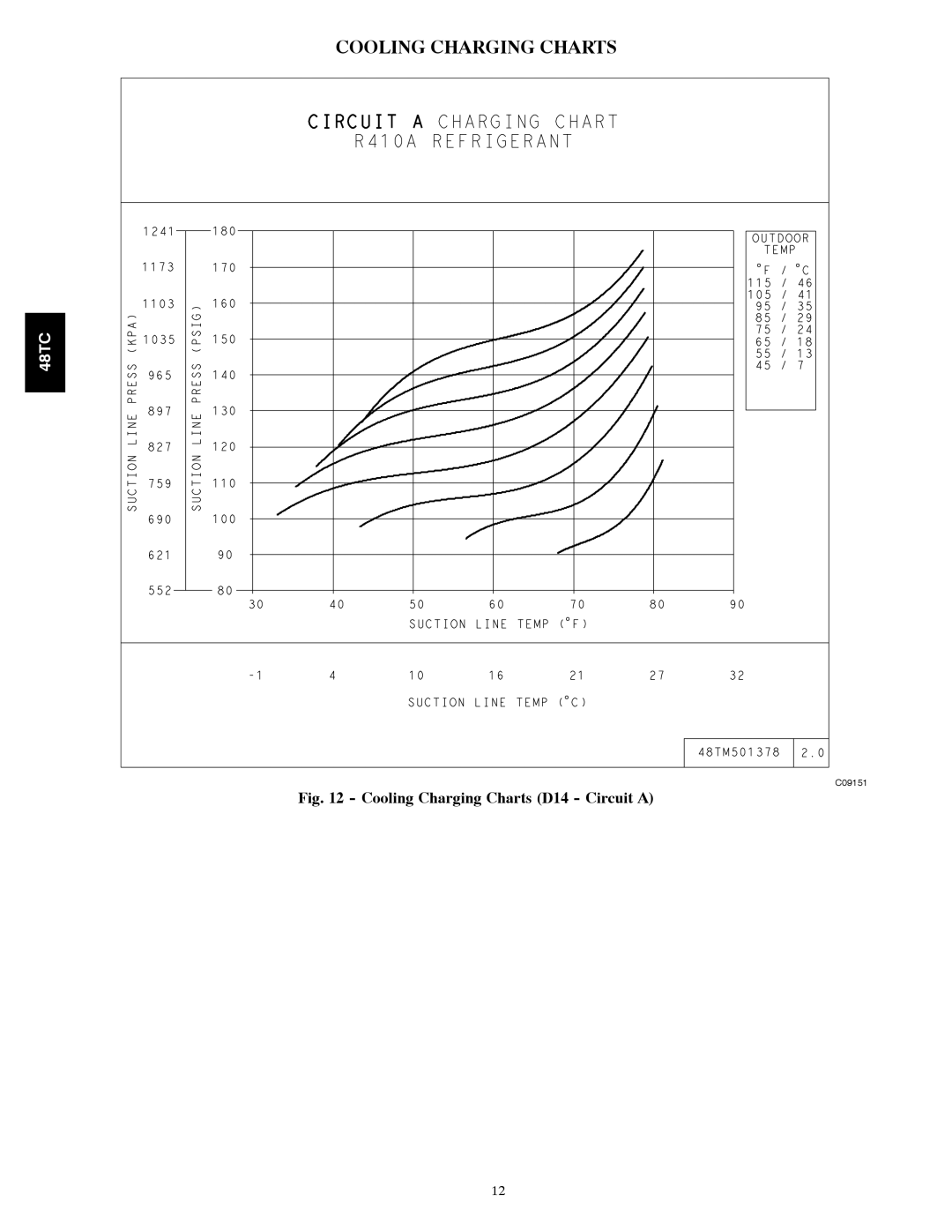
COOLING CHARGING CHARTS
48TC
C09151
Fig. 12 - Cooling Charging Charts (D14 - Circuit A)
12
Page 11
Page 13
Page 12
Image 12
Page 11
Page 13
Contents
Table of Contents
Safety Considerations
Unit Arrangement and Access
General
What to do if you smell gas
Routine Maintenance
Seasonal Maintenance
Supply FAN Blower Section
Supply Fan Belt-Drive
Manual Outside Air Hood Screen
Adjustable-Pitch Pulley on Motor
Supply-Fan Pulley Adjustment Bearings
Coil Maintenance and Cleaning Recommendation
Periodic Clean Water Rinse
Cooling
Condenser Coil
Routine Cleaning of Novation Condenser Coil Surfaces
Routine Cleaning of Evaporator Coil Sufaces
Refrigerant System Pressure Access Ports
Puronr R-410A Refrigerant
Refrigerant Charge
Seatcore
Cooling Charging Charts
Cooling Charging Charts D08
Cooling Charging Charts D12
Cooling Charging Charts D14 Circuit a
Cooling Charging Charts D14 Circuit B
Cooling Service Analysis
Problem Cause Remedy
Condenser-Fan Adjustment D08-D12 size
Condenser-Fan Adjustment D14 size
Troubleshooting Cooling System
Compressors
Non-Powered Type
Unit-Powered Type
Convenience Outlets
Duty Cycle
Smoke Detectors
Smoke Detector Locations
Typical Supply Air Smoke Detector Sensor Location
Completing Installation of Return Air Smoke Sensor
Fiop Smoke Detector Wiring and Response
Sensor Alarm Test
Sensor Alarm Test Procedure
Controller Alarm Test
Sensor and Controller Tests
Controller Alarm Test Procedure
Dirty Controller Test Procedure
Dirty Sensor Test Procedure
To Configure the Dirty Sensor Test Operation
Detector Cleaning
SD-TRK4 Remote Alarm Test Procedure
Remote Test/Reset Station Dirty Sensor Test
Dirty Sensor Test Using an SD-TRK4
Troubleshooting
Protective Devices
Compressor Protection
GAS Heating System
Control Circuit
Fuel Types and Pressures
Flue Gas Passageways
Combustion-Air Blower
Burners and Igniters
Main Burners
Cleaning and Adjustment
Check Unit Operation and Make Necessary Adjustments
Limit Switch
LED Error Code Description
LED Indication Error Code Description
Burner Ignition
Orifice Replacement
Gas Valve
Integrated Gas Control IGC Board IGC Connections
Outputs
Orifice Sizes
Altitude Compensation
Orifice Carrier Drill Drill Size Part Number
Elevation
Troubleshooting Heating System
Minimum Heating Entering Air Temperature
Heating Service Analysis
Problem Cause Remedy
IGC Board LED Alarm Codes
IGC
Condenser Coil Service
Repairing Novation Condenser Tube Leaks
Replacing Novation Condenser Coil
PREMIERLINKt Control
Typical PremierLinkt System Control Wiring Diagram
55 Space Temperature Sensor Wiring
Temp Resistance
Space Sensor Mode
TB1 Terminal Field Connection Input Signal
PremierLink Sensor Usage
Thermostat Mode
56 Internal Connections
Lctb
Indoor CO2 Sensor 33ZCSENCO2 Connections
PremierLink Filter Switch Connection
Signal Type CCN BUS Wire CCN Plug PIN Color Number
RTU-MP Control System
Recommended Cables
Color Code Recommendations
RTU-MP Multi-Protocol Control Board
Typical RTU-MP System Control Wiring Diagram
Configurable Inputs
RTU-MP Controller Inputs and Outputs
Point Name
Type of I/O Connection PIN Name Numbers Inputs
Space Temperature SPT Sensors
RTU-MP T-55 Sensor Connections
RTU-MP / Indoor CO2 Sensor 33ZCSENCO2 Connections
Connecting Discrete Inputs
Power Exhaust output
Communication Wiring Protocols
RTU-MP Troubleshooting
BACview6 Handheld Connections
LEDs
Troubleshooting Alarms
Alarms
BACnet MS/TP
Module Status Report Modstat Example
Basic Protocol Troubleshooting
Modbus
Manufacture Date
Code Name Meaning
ECONOMI$ER Systems
EconoMi$er IV Component Locations
EconoMi$er IV Wiring
EconoMi$er
EconoMi$er IV Input/Output Logic
Inputs Outputs
Supply Air Temperature SAT Sensor
Outdoor Air Lockout Sensor
EconoMi$er IV Control Modes
Outdoor Dry Bulb Changeover
Differential Dry Bulb Control
Outdoor Enthalpy Changeover
Exhaust Setpoint Adjustment
Indoor Air Quality IAQ Sensor Input
Minimum Position Control
Damper Movement
Thermostats
Demand Control Ventilation DCV
CO2 Sensor Configuration
CO2 Sensor Standard Settings
Analog CO2
DCV Demand Controlled Ventilation and Power Exhaust
EconoMi$er IV Sensor Usage
EconoMi$er IV Preparation
Differential Enthalpy
Wiring Diagrams
EconoMi$er IV Troubleshooting Completion
DCV Minimum and Maximum Position
Supply-Air Sensor Input
48TC Typical Unit Wiring Diagram Power D08, 208/230-3-60
48TC Typical Unit Wiring Diagram Control D08, 208/230-3-60
PRE-START-UP
START-UP, General
Unit Preparation
Gas Piping
Internal Wiring
Refrigerant Service Ports
Return-Air Filters
Outdoor-Air Inlet Screens
Field Service Test
START-UP, RTU-MP Control
Ventilation Continuous Fan
Perform System Check-Out
Configuration
Cooling/Econ SAT Low Setpt
Cooling Lockout Temp
Heating Heating SAT High Setpt
Heating Lockout Temp
Power Exhaust Setpt
T55/56 Override Duration
IAQ Low Reference @ 4mA
IAQ High Reference @ 20mA
Operating Sequences
Supplemental Controls
PremierLinkt Control
48TC
48TC
Available Cooling Stages
Number Stages Economizer
48TC
48TC
Rooftop Mode Value Linkage Mode
Linkage Modes
Loadshed Command Gas and Electric Heat Units
Always Occupied Default Occupancy
RTU-MP Sequence of Operation
Scheduling
BACnet Schedule
BAS On/Off
DI On/Off
Indoor Fan
Power Exhaust
Fastener Torque Values
Economizer
Indoor Air Quality
Torque Values
Appendix I. Model Number Significance
Model Number Nomenclature
Serial Number Format
Position Number Typical Designates
Appendix II. Physical Data
Physical Data
12.5TONS
Heat Anticipator Setting Amps
Physical Data Heating 12.5TONS
48TC**08 48TC**12 48TC**14 Gas Connection
Natural Gas Heat, Liquid Propane Heat
Appendix III. FAN Performance
CFM RPM BHP
FAN Performance
579
48TC**14
RPM BHP
Pulley Adjustment
Unit MOTOR/DRIVE Motor Pulley Turns Open Combo
Electrical Information
Unit Combustion Power
MCA/MOCP Determination no C.O. or Unpwrd C.O
NOM IFM FAN Motor Exhaust No P.E
Type DISC. Size
Appendix IV. Wiring Diagram List
Wiring Diagrams
Size Voltage Control Power
Appendix V. Motormaster Sensor Locations
Catalog No 48TC-3SM
Unit START-UP Checklist
Preliminary Information
Top
Page
Image
Contents