Configure the unit for Thermostat Mode — Connect to the CCN bus using a CCN service tool and navigate to PremierLink Configuration screen for Operating Mode. Default setting is Sensor Mode (value 1). Change the value to 0 to reconfigure the controller for Thermostat Mode.
When the PremierLink is configured for Thermostat Mode, these functions are not available: Fire Shutdown (FSD), Remote Occupied (RMTOCC), Compressor Safety (CMPSAFE), Supply Fan Status (SFS), and Filter Pressure Switch (FILTER).
Economizer controls —
Outdoor Air Enthalpy Control (PNO HH57AC077) -
The enthalpy control (HH57AC077) is available as a
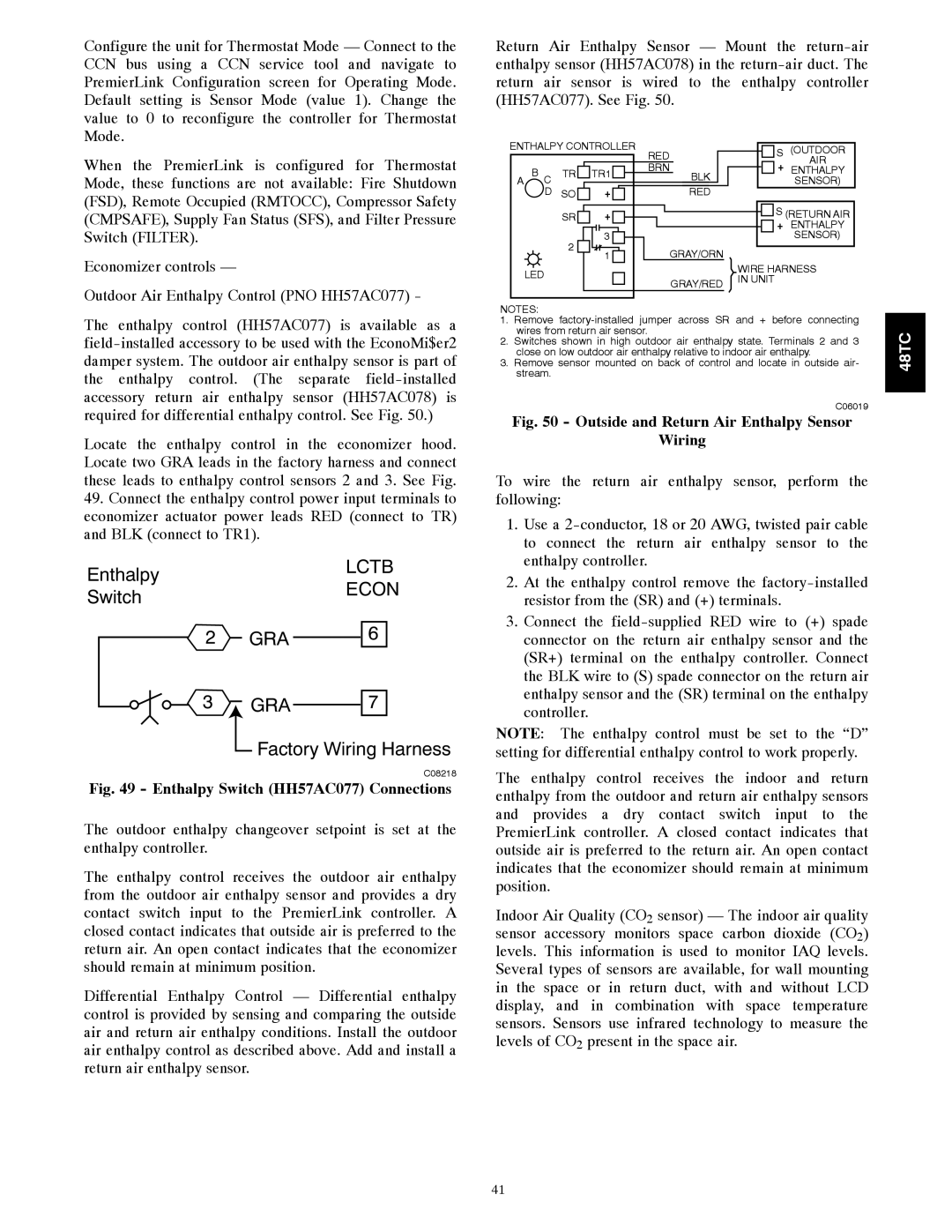
Locate the enthalpy control in the economizer hood. Locate two GRA leads in the factory harness and connect these leads to enthalpy control sensors 2 and 3. See Fig.
49.Connect the enthalpy control power input terminals to economizer actuator power leads RED (connect to TR) and BLK (connect to TR1).
Enthalpy | LCTB | |
ECON | ||
Switch | ||
|
2 | GRA | 6 |
3 | GRA | 7 |
| Factory Wiring Harness | |
|
| C08218 |
Fig. 49 - Enthalpy Switch (HH57AC077) Connections
The outdoor enthalpy changeover setpoint is set at the enthalpy controller.
The enthalpy control receives the outdoor air enthalpy from the outdoor air enthalpy sensor and provides a dry contact switch input to the PremierLink controller. A closed contact indicates that outside air is preferred to the return air. An open contact indicates that the economizer should remain at minimum position.
Differential Enthalpy Control — Differential enthalpy control is provided by sensing and comparing the outside air and return air enthalpy conditions. Install the outdoor air enthalpy control as described above. Add and install a return air enthalpy sensor.
Return Air Enthalpy Sensor — Mount the
ENTHALPY CONTROLLER | RED |
| S (OUTDOOR | ||||
|
|
|
|
| + | AIR | |
|
|
|
| BRN |
| ||
| B C | TR | TR1 | BLK | ENTHALPY | ||
A |
|
| SENSOR) | ||||
| D | SO | + |
| RED |
|
|
|
| SR | + |
|
| S (RETURN AIR | |
|
|
|
|
|
| + | ENTHALPY |
|
| 2 | 3 |
|
|
| SENSOR) |
|
| 1 |
| GRAY/ORN |
|
| |
|
|
|
|
|
| ||
| LED |
|
|
|
| WIRE HARNESS | |
|
|
|
| GRAY/RED | IN UNIT |
| |
|
|
|
|
|
| ||
|
|
|
|
|
|
| |
NOTES:
1.Remove
2.Switches shown in high outdoor air enthalpy state. Terminals 2 and 3 close on low outdoor air enthalpy relative to indoor air enthalpy.
3.Remove sensor mounted on back of control and locate in outside air- stream.
C06019
Fig. 50 - Outside and Return Air Enthalpy Sensor
Wiring
To wire the return air enthalpy sensor, perform the following:
1.Use a
2.At the enthalpy control remove the
3.Connect the
NOTE: The enthalpy control must be set to the “D” setting for differential enthalpy control to work properly.
The enthalpy control receives the indoor and return enthalpy from the outdoor and return air enthalpy sensors and provides a dry contact switch input to the PremierLink controller. A closed contact indicates that outside air is preferred to the return air. An open contact indicates that the economizer should remain at minimum position.
Indoor Air Quality (CO2 sensor) — The indoor air quality sensor accessory monitors space carbon dioxide (CO2) levels. This information is used to monitor IAQ levels. Several types of sensors are available, for wall mounting in the space or in return duct, with and without LCD display, and in combination with space temperature sensors. Sensors use infrared technology to measure the levels of CO2 present in the space air.
48TC
41