Maintenance
Periodically test the GFCI receptacle by pressing the TEST button on the face of the receptacle. This should cause the internal circuit of the receptacle to trip and open the receptacle. Check for proper grounding wires and power line phasing if the GFCI receptacle does not trip as required. Press the RESET button to clear the tripped condition.
Fuse On Powered Type
The factory fuse is a Bussman “Fusetron”
Using Unit-Mounted Convenience Outlets
Units with
SMOKE DETECTORS
Smoke detectors are available as
System
The smoke detector system consists of a
Controller
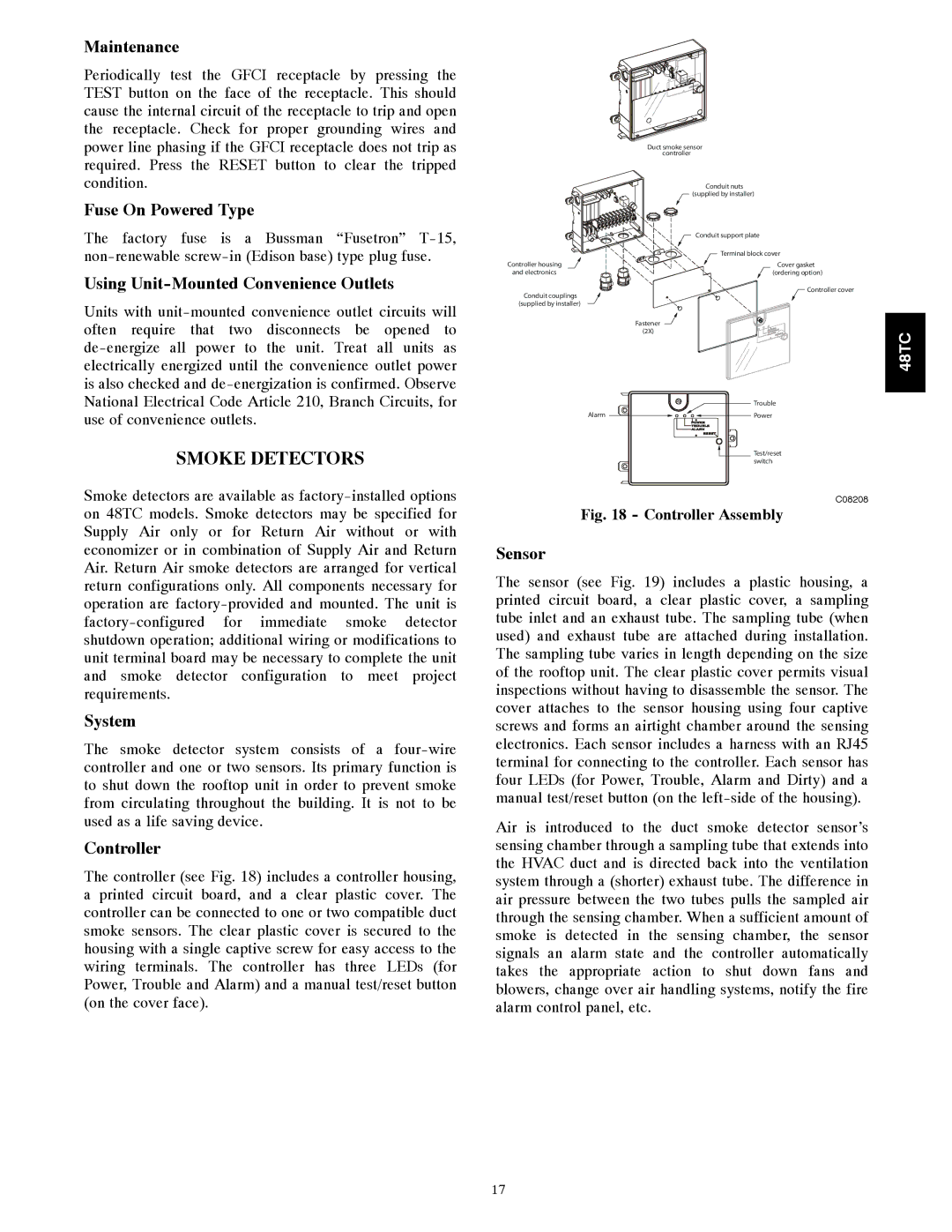
The controller (see Fig. 18) includes a controller housing, a printed circuit board, and a clear plastic cover. The controller can be connected to one or two compatible duct smoke sensors. The clear plastic cover is secured to the housing with a single captive screw for easy access to the wiring terminals. The controller has three LEDs (for Power, Trouble and Alarm) and a manual test/reset button (on the cover face).
Duct smoke sensor
| controller |
| Conduit nuts |
| (supplied by installer) |
| Conduit support plate |
| Terminal block cover |
Controller housing | Cover gasket |
and electronics | (ordering option) |
Conduit couplings | Controller cover |
| |
(supplied by installer) |
|
| Fastener |
| (2X) |
| Trouble |
Alarm | Power |
| Test/reset |
| switch |
C08208
Fig. 18 - Controller Assembly
Sensor
The sensor (see Fig. 19) includes a plastic housing, a printed circuit board, a clear plastic cover, a sampling tube inlet and an exhaust tube. The sampling tube (when used) and exhaust tube are attached during installation. The sampling tube varies in length depending on the size of the rooftop unit. The clear plastic cover permits visual inspections without having to disassemble the sensor. The cover attaches to the sensor housing using four captive screws and forms an airtight chamber around the sensing electronics. Each sensor includes a harness with an RJ45 terminal for connecting to the controller. Each sensor has four LEDs (for Power, Trouble, Alarm and Dirty) and a manual test/reset button (on the
Air is introduced to the duct smoke detector sensor’s sensing chamber through a sampling tube that extends into the HVAC duct and is directed back into the ventilation system through a (shorter) exhaust tube. The difference in air pressure between the two tubes pulls the sampled air through the sensing chamber. When a sufficient amount of smoke is detected in the sensing chamber, the sensor signals an alarm state and the controller automatically takes the appropriate action to shut down fans and blowers, change over air handling systems, notify the fire alarm control panel, etc.
48TC
17