48TC
Table 15 – Thermistor Resistance vs Temperature Values for Space Temperature Sensor, Supply Air Temperature Sensor, and Outdoor Air Temperature Sensor
TEMP | TEMP | RESISTANCE |
(C) | (F) | (Ohms) |
335,651 | ||
242,195 | ||
|
|
|
176,683 | ||
130,243 | ||
96,974 | ||
|
|
|
5 | 72,895 | |
14 | 55,298 | |
|
|
|
23 | 42,315 | |
|
|
|
0 | 32 | 32,651 |
5 | 41 | 25,395 |
|
|
|
10 | 50 | 19,903 |
15 | 59 | 15,714 |
20 | 68 | 12,494 |
|
|
|
25 | 77 | 10,000 |
30 | 86 | 8,056 |
35 | 95 | 6,530 |
|
|
|
40 | 104 | 5,325 |
45 | 113 | 4,367 |
|
|
|
50 | 122 | 3,601 |
|
|
|
55 | 131 | 2,985 |
60 | 140 | 2,487 |
|
|
|
65 | 149 | 2,082 |
|
|
|
70 | 158 | 1,752 |
NOTE: The sensor must be mounted in the discharge airstream downstream of the cooling coil and any heating devices. Be sure the probe tip does not come in contact with any of the unit’s heater surfaces.
Outdoor Air Temperature (OAT) Sensor — The OAT is
EconoMi$er 2 — The PremierLink control is used with EconoMi$er 2 (option or accessory) for outdoor air management. The damper position is controlled directly by the PremierLink control; EconoMi$er 2 has no internal logic device.
Outdoor air management functions can be enhanced with
Enthalpy control (outdoor air or differential sensors) Space CO2 sensor
Outdoor air CO2 sensor
Refer to Table 16 for accessory part numbers.
Field connections — Field connections for accessory sensor and input devices are made at the
Table 17 provides a summary of field connections for units equipped with Space Sensor. Table 18 provides a summary of field connections for units equipped with Space Thermostat.
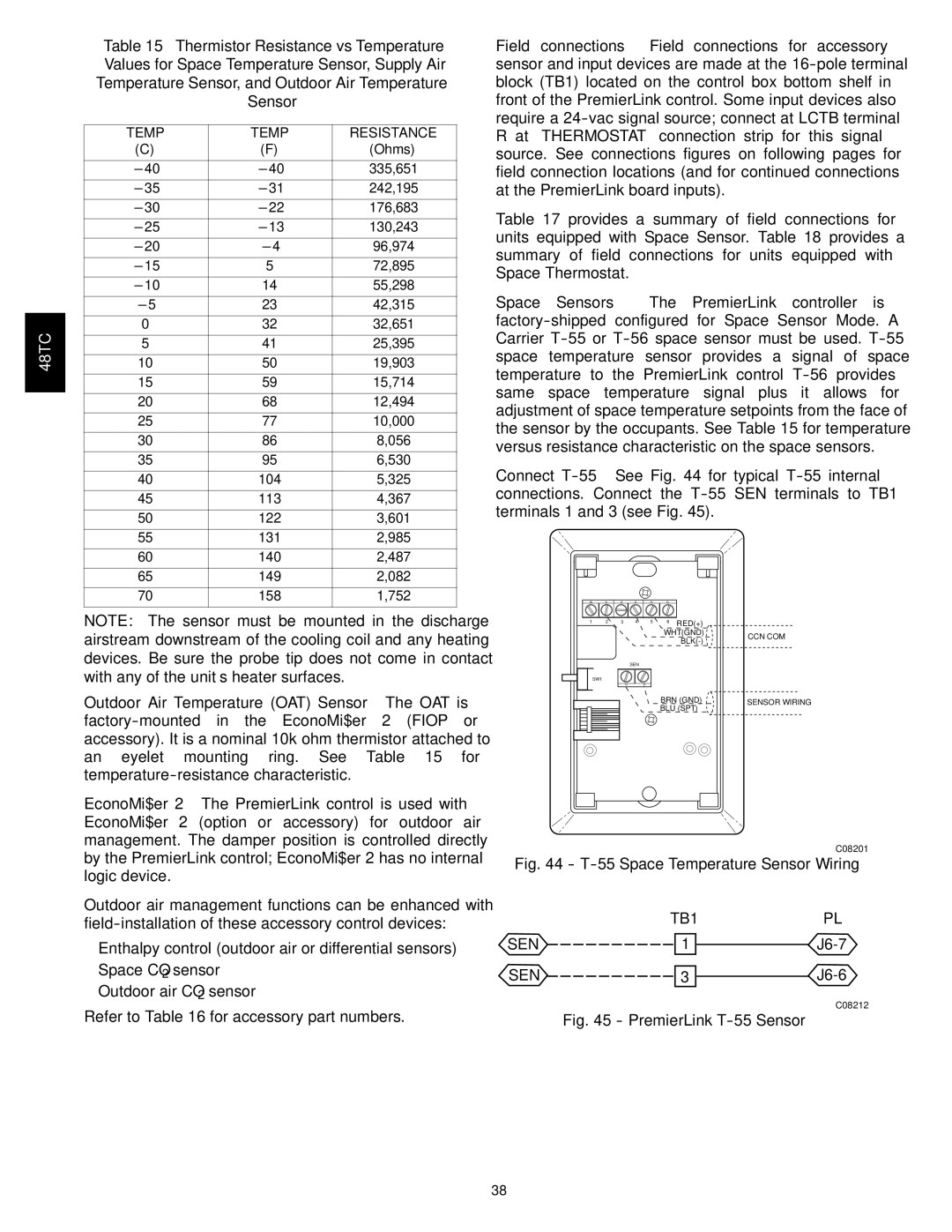
Space Sensors — The PremierLink controller is
Connect
1 | 2 | 3 | 4 | 5 | 6 | RED(+) |
|
|
|
|
|
| WHT(GND) | CCN COM | |
|
|
|
|
|
| ||
|
|
|
|
|
|
| |
|
|
| SEN |
|
|
|
|
| SW1 |
|
|
|
|
|
|
|
|
|
|
| BRN (GND) | SENSOR WIRING | |
|
|
|
|
| BLU (SPT) |
| |
C08201
Fig. 44 - T-55 Space Temperature Sensor Wiring
TB1PL
SEN ![]() 1
1 ![]()
![]()
SEN ![]() 3
3 ![]()
![]()
C08212
Fig. 45 - PremierLink T-55 Sensor
38