48TC
Power Exhaust
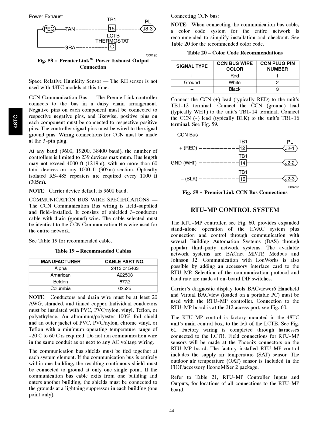
TB1PL
PEC | TAN | 15 |
LCTB
THERMOSTAT
GRA 
 C
C
C08120
Fig. 58 - PremierLinkt Power Exhaust Output
Connection
Space Relative Humidity Sensor — The RH sensor is not used with 48TC models at this time.
CCN Communication Bus — The PremierLink controller connects to the bus in a daisy chain arrangement. Negative pins on each component must be connected to respective negative pins, and likewise, positive pins on each component must be connected to respective positive pins. The controller signal pins must be wired to the signal ground pins. Wiring connections for CCN must be made at the
At any baud (9600, 19200, 38400 baud), the number of controllers is limited to 239 devices maximum. Bus length may not exceed 4000 ft (1219m), with no more than 60 total devices on any
NOTE: Carrier device default is 9600 baud.
COMMUNICATION BUS WIRE SPECIFICATIONS — The CCN Communication Bus wiring is
See Table 19 for recommended cable.
Table 19 – Recommended Cables
MANUFACTURER | CABLE PART NO. |
Alpha | 2413 or 5463 |
American | A22503 |
Belden | 8772 |
Columbia | 02525 |
NOTE: Conductors and drain wire must be at least 20 AWG, stranded, and tinned copper. Individual conductors must be insulated with PVC, PVC/nylon, vinyl, Teflon, or polyethylene. An aluminum/polyester 100% foil shield and an outer jacket of PVC, PVC/nylon, chrome vinyl, or Teflon with a minimum operating temperature range of
The communication bus shields must be tied together at each system element. If the communication bus is entirely within one building, the resulting continuous shield must be connected to ground at only one single point. If the communication bus cable exits from one building and enters another building, the shields must be connected to the grounds at a lightning suppressor in each building (one point only).
Connecting CCN bus:
NOTE: When connecting the communication bus cable, a color code system for the entire network is recommended to simplify installation and checkout. See Table 20 for the recommended color code.
Table 20 – Color Code Recommendations
SIGNAL TYPE | CCN BUS WIRE | CCN PLUG PIN | |
COLOR | NUMBER | ||
| |||
|
|
| |
+ | Red | 1 | |
|
|
| |
Ground | White | 2 | |
|
|
| |
Black | 3 |
Connect the CCN (+) lead (typically RED) to the unit’s
CCN Bus |
|
|
|
| TB1 | PL | |
+ (RED) | 12 |
| |
| |||
TB1
GND (WHT) ![]() 14
14 ![]()
![]()
TB1
– (BLK) ![]() 16
16 ![]()
![]()
C08276
Fig. 59 - PremierLink CCN Bus Connections
RTU-MP CONTROL SYSTEM
The
Carrier’s diagnostic display tools BACviewer6 Handheld and Virtual BACview (loaded on a portable PC) must be used with the
The
61.Factory wiring is completed through harnesses connected to the LCTB. Field connections for
Refer to Table 21,
44