48TC
The same equation can be used to determine the occupied or maximum ventilation rate to the building. For example, an output of 3.6 volts to the actuator provides a base ventilation rate of 5% and an output of 6.7 volts provides the maximum ventilation rate of 20% (or base plus 15 cfm per person). Use Fig. 83 to determine the maximum setting of the CO2 sensor. For example, an 1100 ppm setpoint relates to a 15 cfm per person design. Use the 1100 ppm curve on Fig. 83 to find the point when the CO2 sensor output will be 6.7 volts. Line up the point on the graph with the left side of the chart to determine that the range configuration for the CO2 sensor should be 1800 ppm. The EconoMi$er IV controller will output the 6.7 volts from the CO2 sensor to the actuator when the CO2 concentration in the space is at 1100 ppm. The DCV setpoint may be left at 2 volts since the CO2 sensor voltage will be ignored by the EconoMi$er IV controller until it rises above the 3.6 volt setting of the minimum position potentiometer.
Once the fully occupied damper position has been determined, set the maximum damper demand control ventilation potentiometer to this position. Do not set to the maximum position as this can result in
CO2 Sensor Configuration
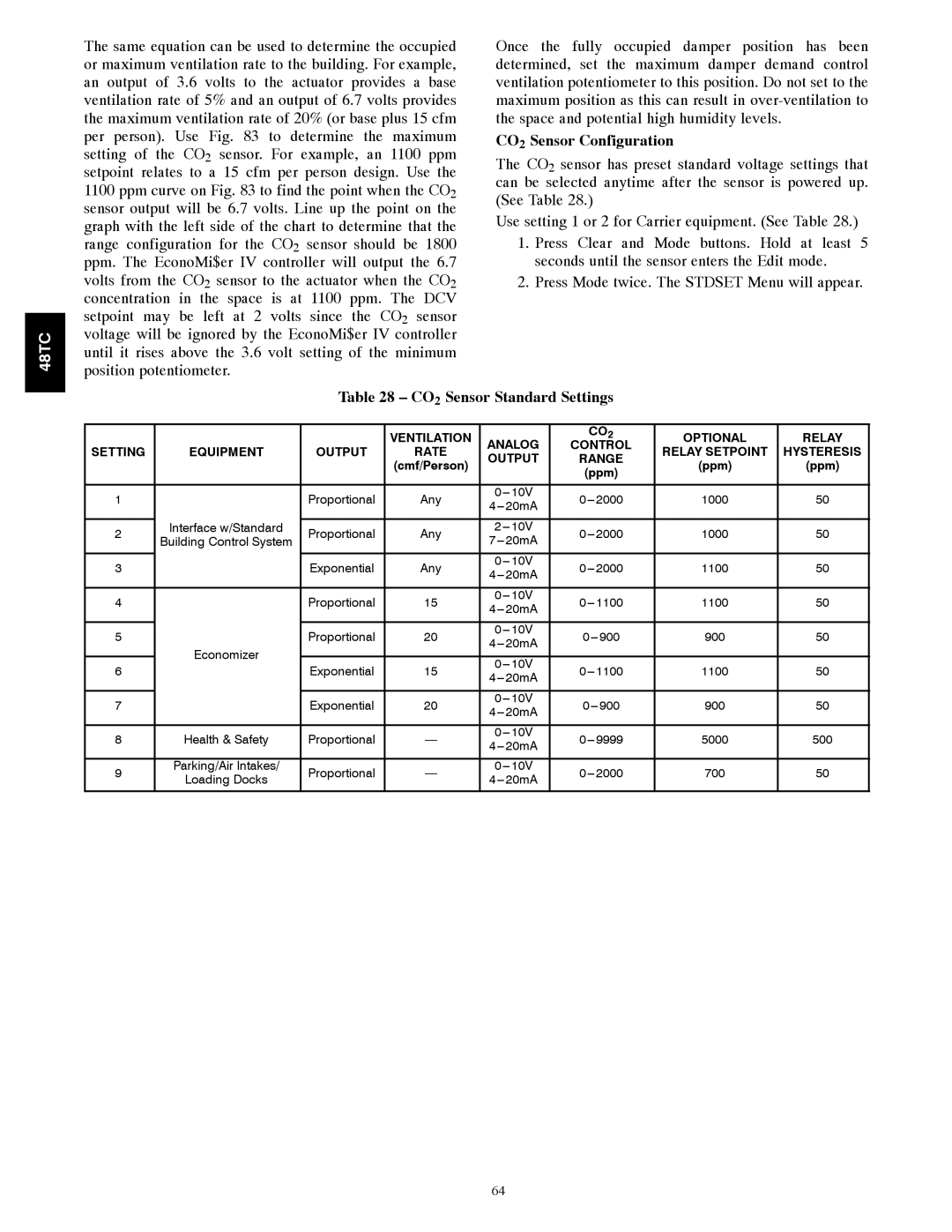
The CO2 sensor has preset standard voltage settings that can be selected anytime after the sensor is powered up. (See Table 28.)
Use setting 1 or 2 for Carrier equipment. (See Table 28.)
1.Press Clear and Mode buttons. Hold at least 5 seconds until the sensor enters the Edit mode.
2.Press Mode twice. The STDSET Menu will appear.
Table 28 – CO2 Sensor Standard Settings
|
|
| VENTILATION | ANALOG | CO2 | OPTIONAL | RELAY | |
SETTING | EQUIPMENT | OUTPUT | RATE | CONTROL | RELAY SETPOINT | HYSTERESIS | ||
OUTPUT | RANGE | |||||||
|
|
| (cmf/Person) | (ppm) | (ppm) | |||
|
|
|
| (ppm) | ||||
|
|
|
|
|
|
| ||
|
|
|
|
|
|
|
| |
1 |
| Proportional | Any | 1000 | 50 | |||
| ||||||||
|
|
|
|
|
|
| ||
| Interface w/Standard |
|
|
|
|
|
| |
2 | Proportional | Any | 1000 | 50 | ||||
Building Control System | ||||||||
|
|
|
|
|
| |||
|
|
|
|
|
|
|
| |
3 |
| Exponential | Any | 1100 | 50 | |||
| ||||||||
|
|
|
|
|
|
| ||
|
|
|
|
|
|
|
| |
4 |
| Proportional | 15 | 1100 | 50 | |||
| ||||||||
|
|
|
|
|
|
| ||
|
|
|
|
|
|
|
| |
5 |
| Proportional | 20 | 900 | 50 | |||
| ||||||||
| Economizer |
|
|
|
|
| ||
|
|
|
|
|
|
| ||
6 | Exponential | 15 | 1100 | 50 | ||||
| ||||||||
| ||||||||
|
|
|
|
|
|
| ||
|
|
|
|
|
|
|
| |
7 |
| Exponential | 20 | 900 | 50 | |||
| ||||||||
|
|
|
|
|
|
| ||
|
|
|
|
|
|
|
| |
8 | Health & Safety | Proportional | — | 5000 | 500 | |||
|
|
|
|
|
|
| ||
|
|
|
|
|
|
|
| |
9 | Parking/Air Intakes/ | Proportional | — | 700 | 50 | |||
Loading Docks | ||||||||
|
|
|
|
|
| |||
|
|
|
|
|
|
|
|
64