Carrier 48TC*D08 appendix Convenience Outlets, Non-PoweredType, Unit-PoweredType, Duty Cycle

Models: 48TC*D08

1 98
Download 98 pages 26.51 Kb
Page 16
Image 16
CONVENIENCE OUTLETS

CONVENIENCE OUTLETS


!

WARNING


ELECTRICAL OPERATION HAZARD


Failure to follow this warning could result in personal


injury or death.


Units with convenience outlet circuits may use


multiple disconnects. Check convenience outlet for


power status before opening unit for service. Locate


its disconnect

switch, if appropriate, and open it.


Tag-out this switch, if necessary.


Two types of convenience outlets are offered on 48TC


models: Non-powered and unit-powered. Both types

48TC


provide a 125-volt GFCI (ground-fault circuit-interrupter)


duplex receptacle rated at 15-A behind a hinged


waterproof access cover, located on the end panel of the


unit. (See Fig. 16.)


Pwd-CO Transformer

Conv Outlet

GFCI

Pwd-CO

Fuse Fig. 16 - Convenience Outlet Location

Switch

C08128

Fig. 16 - Convenience Outlet Location

Non-Powered Type

This type requires the field installation of a general-purpose 125-volt 15-A circuit powered from a source elsewhere in the building. Observe national and local codes when selecting wire size, fuse or breaker requirements and disconnect switch size and location. Route 125-v power supply conductors into the bottom of the utility box containing the duplex receptacle.

Unit-Powered Type

Aunit-mounted transformer is factory-installed to stepdown the main power supply voltage to the unit to 115-v at the duplex receptacle. This option also includes a manual switch with fuse, located in a utility box and mounted on a bracket behind the convenience outlet; access is through the unit’s control box access panel. (See Fig. 16.)

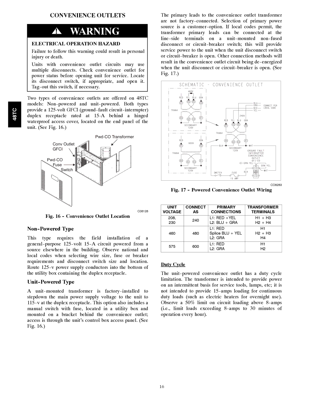
The primary leads to the convenience outlet transformer are not factory-connected. Selection of primary power source is a customer-option. If local codes permit, the transformer primary leads can be connected at the line-side terminals on a unit-mounted non-fused disconnect or circuit-breaker switch; this will provide service power to the unit when the unit disconnect switch or circuit-breaker is open. Other connection methods will result in the convenience outlet circuit being de-energized when the unit disconnect or circuit-breaker is open. (See Fig. 17.)

CO8283

Fig. 17 - Powered Convenience Outlet Wiring

UNIT

CONNECT

PRIMARY

TRANSFORMER

VOLTAGE

AS

CONNECTIONS

TERMINALS


208,

240

L1: RED +YEL

H1 + H3

230

L2: BLU + GRA

H2 + H4


L1: RED

H1

460

480

Splice BLU + YEL

H2 + H3


L2: GRA

H4


575

600

L1: RED

H1

L2: GRA

H2


Duty Cycle

The unit-powered convenience outlet has a duty cycle limitation. The transformer is intended to provide power on an intermittent basis for service tools, lamps, etc; it is not intended to provide 15-amps loading for continuous duty loads (such as electric heaters for overnight use). Observe a 50% limit on circuit loading above 8-amps (i.e., limit loads exceeding 8-amps to 30 minutes of operation every hour).

16

Page 16
Image 16
Carrier 48TC*D08 appendix Convenience Outlets, Non-PoweredType, Unit-PoweredType, Convenience Outlet Location, Duty Cycle