48TC
Table 18 – Thermostat Mode
TB1 TERMINAL | FIELD CONNECTION | INPUT SIGNAL |
1 | RAT SEN | Analog (10k thermistor) |
2 | G | Discrete, 24VAC |
3 | RAT SEN | Analog (10k thermistor) |
4 | Y1 | Discrete, 24VAC |
5 |
|
|
6 | Y2 | Discrete, 24VAC |
7 | Analog, 24VDC | |
8 | W1 | Discrete, 24VAC |
9 | IAQ | Analog, |
10 | W2 | Discrete, 24VAC |
11 | IAQ | Analog, |
12 | CCN + (RED) | Digital, 5VDC |
13 | OAQ | Analog, |
14 | CCN Gnd (WHT) | Digital, 5VDC |
15 | AUX OUT (Power Exhaust) | (Output) Discrete 24VAC |
16 | CCN | Digital, 5VDC |
LEGEND: |
|
|
| |
CCN | Carrier Comfort Network (communication bus) | RH | ||
G | Thermostat Fan | W1 | ||
IAQ | Indoor Air Quality (CO2) | W2 | ||
OAQ | Outdoor Air Quality (CO2) | Y1 | ||
RAT | Return Air Temperature | Y2 | ||
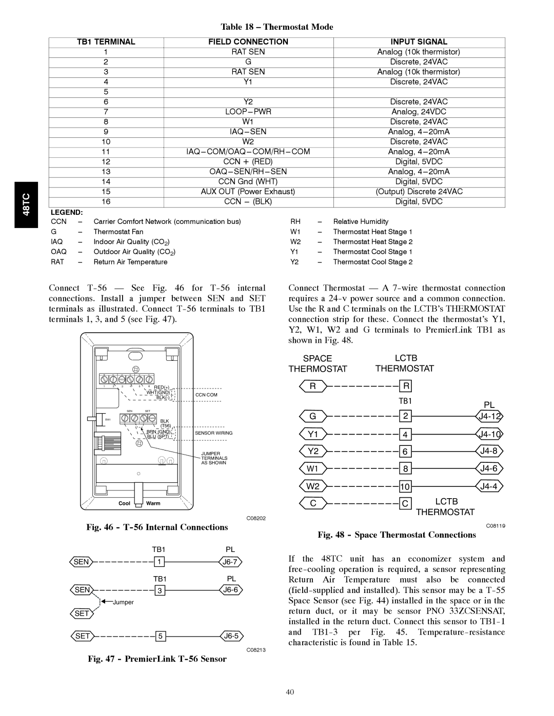
Connect
1 | 2 | 3 | 4 | 5 | 6 | RED(+) |
|
|
|
|
|
| WHT(GND) | CCN COM | |
|
|
|
|
|
| ||
|
|
|
|
|
|
| |
|
|
| SEN |
| SET |
|
|
| SW1 |
|
|
|
| BLK |
|
|
|
|
|
|
|
| |
|
|
|
|
|
| (T56) |
|
|
|
|
|
| BRN (GND) | SENSOR WIRING | |
|
|
|
|
| BLU (SPT) |
| |
|
|
|
|
|
|
| JUMPER |
|
|
|
|
|
|
| TERMINALS |
|
|
|
|
|
|
| AS SHOWN |
Cool Warm
C08202
Fig. 46 - T-56 Internal Connections
| TB1 | PL |
SEN | 1 | |
| TB1 | PL |
SEN | 3 |
![]()
![]() Jumper
Jumper
SET
SET ![]() 5
5 ![]()
![]()
C08213
Fig. 47 - PremierLink T-56 Sensor
Connect Thermostat — A
SPACELCTB
THERMOSTAT THERMOSTAT
R | R |
|
| TB1 | PL |
|
| |
G | 2 |
Y1 ![]() 4
4 ![]()
![]()
Y2 ![]() 6
6 ![]()
![]()
W1 ![]() 8
8 ![]()
![]()
W2 ![]() 10
10 ![]()
![]()
C | C | LCTB |
THERMOSTAT
C08119
Fig. 48 - Space Thermostat Connections
If the 48TC unit has an economizer system and
40