48TC
Temperature Compensated Start — This function will run when the controller is in unoccupied state and will calculate early start bias time (SBT) based on space temperature deviation from occupied setpoints in minutes per degree. The following conditions will be met for the function to run:
S Unit is in unoccupied state S Next occupied time is valid S Current time of day is valid
SValid space temperature reading is available (from sensor or linkage thermostat)
S Cool Start Bias (KCOOL) and Heat Bias Start (KHEAT) > 0 in the CONFIG configuration table
The SBT is calculated by one of the following formulas depending on temperature demand:
If SPT > OCSP then SBT = (SPT - OCSP) * KCOOL If SPT < OHSP then SPT = (OHSP - SPT) * KHEAT.
The calculated start bias time can range from 0 to 255 minutes. When SBT is greater than 0 the function will subtract the SBT from the next occupied time to calculate a new start time. When a new start time is reached, the Temperature Compensated Start mode is started. This mode energizes the fan and the unit will operate as though it is in occupied state. Once set, Temperature Compensated Start mode will stay on until the unit returns to occupied state. If either Unoccupied Free Cool or IAQ
Door Switch — The Door Switch function is designed to disable mechanical heating and cooling outputs when the REMOCC contact input is closed (in the ON state) after a programmed time delay. The fan will continue to operate based on the current mode and the ASHRAE 90.1 Supply Fan setting. The delay is programmable from 2 to 20 minutes by setting the Remote Cont/Door Switch decision in the SERVICE table to a value equal to the number of minutes desired. When the contact is open (in the OFF state), the PremierLink controller will resume normal temperature control.
This application is designed for use in schools or other public places where a door switch can be installed to monitor the opening of a door for an extended period of time. The controller will disable mechanical cooling and heating when the door is open for a programmed amount of time.
This function can also be used to monitor a high condensate level switch when installed on a water source heat pump to disable mechanic cooling in case of a plugged evaporator condensate pan drain.
Linkage — The Linkage function in the PremierLink controller is available for applications using a Linkage thermostat or the 3V control system. If using the Linkage thermostat, both the PremierLink controller and the stat must be on the same CCN bus. When used as the air source for a 3V control system, the PremierLink controller is not required to be on the same CCN bus but it is recommended. Linkage will be active when it is initiated from the Linkage thermostat or the 3V Linkage Coordinator through CCN communications and requires no configuration. Only one device can be linked to the PremierLink controller.
Once Linkage is active, the PremierLink controller’s own SPT, temperature setpoints, and occupancy are ignored and the controller will use the information provided by the remote linkage device. The following information will be received from the remote linked device and can be viewed in the maintenance display table:
S Supervisory Element S Supervisory Bus
S Supervisory Block
S Average Occupied Heat Setpoint
S Average Occupied Cool Setpoint
S Average Unoccupied Heat Setpoint
S Average Unoccupied Cool Setpoint S Average Zone Temp
S Average Occupied Zone Temp S Occupancy Status
In return, the PremierLink controller will provide its SAT and operating mode to the linked device.
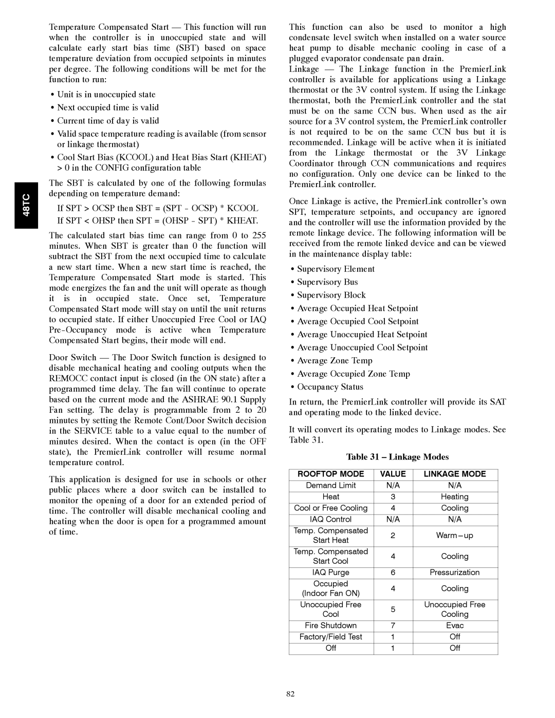
It will convert its operating modes to Linkage modes. See Table 31.
Table 31 – Linkage Modes
ROOFTOP MODE | VALUE | LINKAGE MODE | |
Demand Limit | N/A | N/A | |
Heat | 3 | Heating | |
Cool or Free Cooling | 4 | Cooling | |
|
|
| |
IAQ Control | N/A | N/A | |
Temp. Compensated | 2 | Warm | |
Start Heat | |||
|
| ||
|
|
| |
Temp. Compensated | 4 | Cooling | |
Start Cool | |||
|
| ||
|
|
| |
IAQ Purge | 6 | Pressurization | |
Occupied | 4 | Cooling | |
(Indoor Fan ON) | |||
|
| ||
|
|
| |
Unoccupied Free | 5 | Unoccupied Free | |
Cool | Cooling | ||
| |||
|
|
| |
Fire Shutdown | 7 | Evac | |
Factory/Field Test | 1 | Off | |
Off | 1 | Off | |
|
|
|
82