52S
SERIES
SEQUENCE OF OPERATION
HEAT/COOL UNITS (Figure 50)
Fan Mode Ð With the selector switch set to FAN and the fan switch set to fan cycle, contacts L1 to LO and FCS1 to LS are made.
Cooling (Low) Ð With the selector switch set to low speed cooling and the fan switch set to fan cycle, contacts FCS2 to LO, COMP to FCS1, and COMP to IT3 are made.
NOTE: The contact in low cooling sequence of operation for FCS2 is MED on units built prior to 1996.
Cooling (High) Ð With the selector switch set to high speed cool and the fan switch set to fan cycle, contacts FCS2 to HI, COMP to FCS1, and COMP to IT3 are made.
Heating (Low) Ð With the selector switch set to low speed heat and the fan switch set to fan cycle, contacts FCS2 to LO, IT1 to LS, L2 to HTR, and FCS1 to LS are made.
NOTE: The contact in low heating sequence of operation for FCS2 is MED on units built prior to 1996.
Heating (High) Ð With the selector switch set to high speed heat and the fan switch set to fan cycle, con- tacts FCS2 to HI, IT1 to LS, L2 to HTR, and FCS1 to LS are made.
SWITCH | CONTACTS MADE | |
POSITION | ||
| ||
OFF | FCS TO LS | |
FAN | L1 TO LO*, FCS1 TO LS | |
LO HEAT | FCS2 TO LO, IT1 TO LS, L2 TO HTR, FCS1 TO LS | |
HI HEAT | FCS2 TO HI, IT1 TO LS, L2 TO HTR, FCS1 TO LS | |
LO COOL | FCS2 TO LO, COMP TO FCS1, COMP TO IT3 | |
HI COOL | FCS2 TO HI, COMP TO FCS1, COMP TO IT3 | |
|
|
*L1 to MED, some models.
FIGURE 50 Ð SELECTOR SWITCH CONTACTS,
ALL 52SE AA AND CP MODELS
COOLING ONLY UNITS (Figure 51)
Fan Mode Ð With the selector switch set to FAN and the fan switch set to fan cycle, contact L1 to LO is made.
Cooling (Low) Ð With the selector switch set to low speed cooling and the fan switch set to fan cycle, contacts FCS to LO and L1 to IT3 are made.
NOTE: The contact in low cooling sequence of operation for FCS2 is MED on units built prior to 1996.
Cooling (High) Ð With the selector switch set to high speed cool and the fan switch set to fan cycle, contacts FCS to HI, L1 to IT3 are made.
SWITCH | CONTACTS MADE | ||
POSITION | |||
|
| ||
OFF | NONE | ||
FAN | L1 | TO LO* | |
LO COOL | L1 | TO IT3, FCS TO LO | |
HI COOL | L1 | TO IT3, FCS TO HI | |
|
|
| |
*L1 to MED, some models.
FIGURE 51 Ð SELECTOR SWITCH CONTACTS,
ALL 52SC AA AND CP MODELS
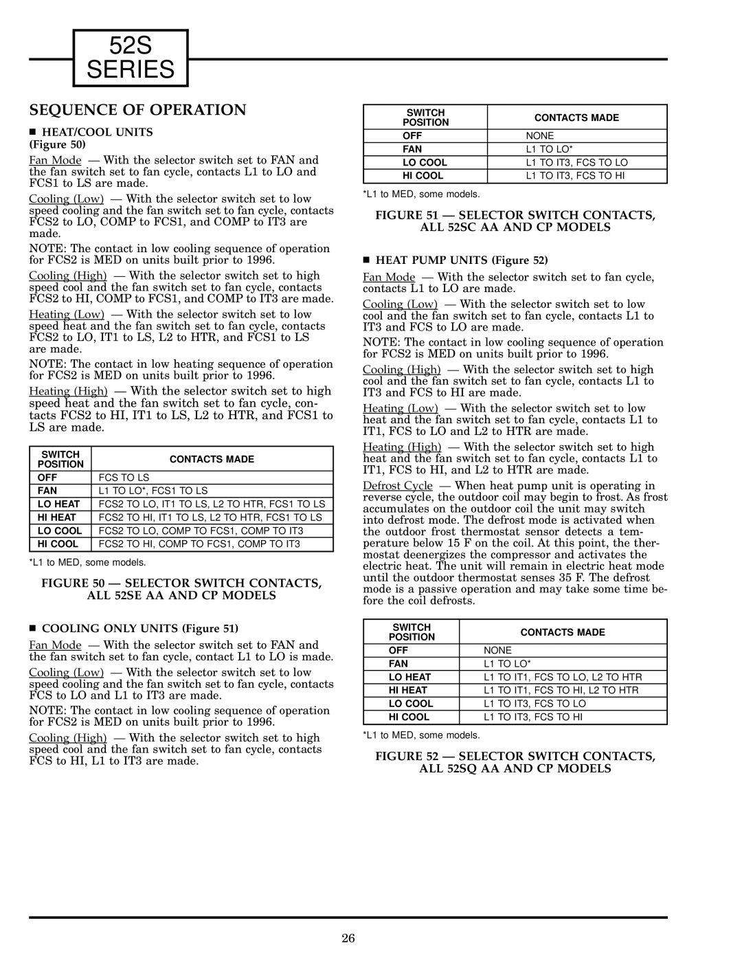
HEAT PUMP UNITS (Figure 52)
Fan Mode Ð With the selector switch set to fan cycle, contacts L1 to LO are made.
Cooling (Low) Ð With the selector switch set to low cool and the fan switch set to fan cycle, contacts L1 to IT3 and FCS to LO are made.
NOTE: The contact in low cooling sequence of operation for FCS2 is MED on units built prior to 1996.
Cooling (High) Ð With the selector switch set to high cool and the fan switch set to fan cycle, contacts L1 to IT3 and FCS to HI are made.
Heating (Low) Ð With the selector switch set to low heat and the fan switch set to fan cycle, contacts L1 to IT1, FCS to LO and L2 to HTR are made.
Heating (High) Ð With the selector switch set to high heat and the fan switch set to fan cycle, contacts L1 to IT1, FCS to HI, and L2 to HTR are made.
Defrost Cycle Ð When heat pump unit is operating in reverse cycle, the outdoor coil may begin to frost. As frost accumulates on the outdoor coil the unit may switch into defrost mode. The defrost mode is activated when the outdoor frost thermostat sensor detects a tem- perature below 15 F on the coil. At this point, the ther- mostat deenergizes the compressor and activates the electric heat. The unit will remain in electric heat mode until the outdoor thermostat senses 35 F. The defrost mode is a passive operation and may take some time be- fore the coil defrosts.
SWITCH |
| CONTACTS MADE |
POSITION |
| |
|
| |
OFF | NONE | |
FAN | L1 | TO LO* |
LO HEAT | L1 | TO IT1, FCS TO LO, L2 TO HTR |
HI HEAT | L1 | TO IT1, FCS TO HI, L2 TO HTR |
LO COOL | L1 | TO IT3, FCS TO LO |
HI COOL | L1 | TO IT3, FCS TO HI |
*L1 to MED, some models.
FIGURE 52 Ð SELECTOR SWITCH CONTACTS,
ALL 52SQ AA AND CP MODELS
26