|
|
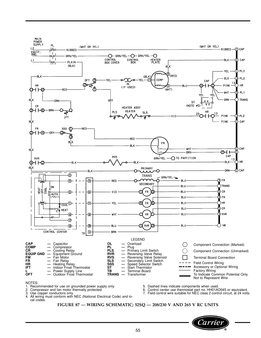
| LEGEND |
| |
CAP | Ð Capacitor | OL | Ð Overload | Component Connection (Marked) | |
COMP | Ð Compressor | PL | Ð Plug |
| |
CR | Ð Cooling Relay | PLS | Ð Primary Limit Switch | Component Connection (Unmarked) | |
EQUIP GND Ð Equipment Ground | RVR | Ð Reversing Valve Relay |
| ||
FM | Ð Fan Motor | RVS | Ð Reversing Valve Solenoid | Terminal Board Connection | |
FR | Ð Fan Relay | SLS | Ð Secondary Limit Switch | Field Control Wiring | |
HR | Ð Heating Relay | SSS | Ð Speed Selector Switch | ||
Accessory or Optional Wiring | |||||
IFT | Ð Indoor Frost Thermostat | ST | Ð Start Thermistor | ||
L | Ð Power Supply Line | TB | Ð Terminal Board | Factory Wiring | |
OFT | Ð Outdoor Frost Thermostat | TRANS Ð Transformer | To Indicate Common Potential Only. | ||
|
|
|
| Not to Represent Wire | |
NOTES:
1.Recommended for use on grounded power supply only.
2.Compressor and fan motor thermally protected.
3.Use copper conductors only.
4.All wiring must conform with NEC (National Electrical Code) and lo- cal codes.
5.Dashed lines indicate components when used.
6.Control center use thermostat part no. HH01AD045 or equivalent.
7.Field control wire suitable for NEC class 2 control circuit, at 24 volts.
FIGURE 87 Ð WIRING SCHEMATIC; 52SQ Ð 208/230 V AND 265 V RC UNITS
55