COMPONENT OPERATION AND TROUBLESHOOTING
TOOLS NEEDED
Flat and Phillips Screw Drivers
Side Cutting Pliers
Before cleaning, servicing, performing maintenance or removing the chassis from the wall sleeve, discon- nect all power to the unit to avoid the possibility of electrical shock and personal injury. Only trained and quali®ed service personnel should perform installation and service procedures on these units. Untrained personnel may perform basic maintenance tasks such as cleaning and replacing ®lters. Refer to GENERAL DISASSEMBLY section of this manual for proper procedures to disconnect power to 52S units.
The Manufacturer reserves the right to discontinue, or change at any time, speci®cations or designs without notice and without incurring obligations.
Consider the following safety issues:
·Prior to performing any service or maintenance on electrical equipment you must Disconnect All
Power.
·New and unfamiliar tasks should be performed under the supervision of an experienced service technician.
·Personal protective equipment, such as safety glasses and work gloves, should be worn.
·The ¯oor around the work area should be clean and free of debris.
·Make sure tools are the correct tools for job, and that they are working properly and in good condition.
·The 52S unit may weigh up to 150 pounds. Use a lift- ing device or ask for assistance if the unit must be moved.
INDOOR THERMOSTAT (Heat/Cool and Cool Only Units) (Figure 53) Ð The thermostat maintains the
selected temperature by cycling the compressor on and off during cooling operation and the electric heater during heating operation. The thermostat DOES NOT switch from heating to cooling, or cooling to heating. If the switch is in the CYCLE position, then the fan will be cycled off when the thermostat satis®es. A bulb heater was incorporated on models built prior to 1996 to help provide closer temperature control. This heater does not affect the mechanical operation of the switch.
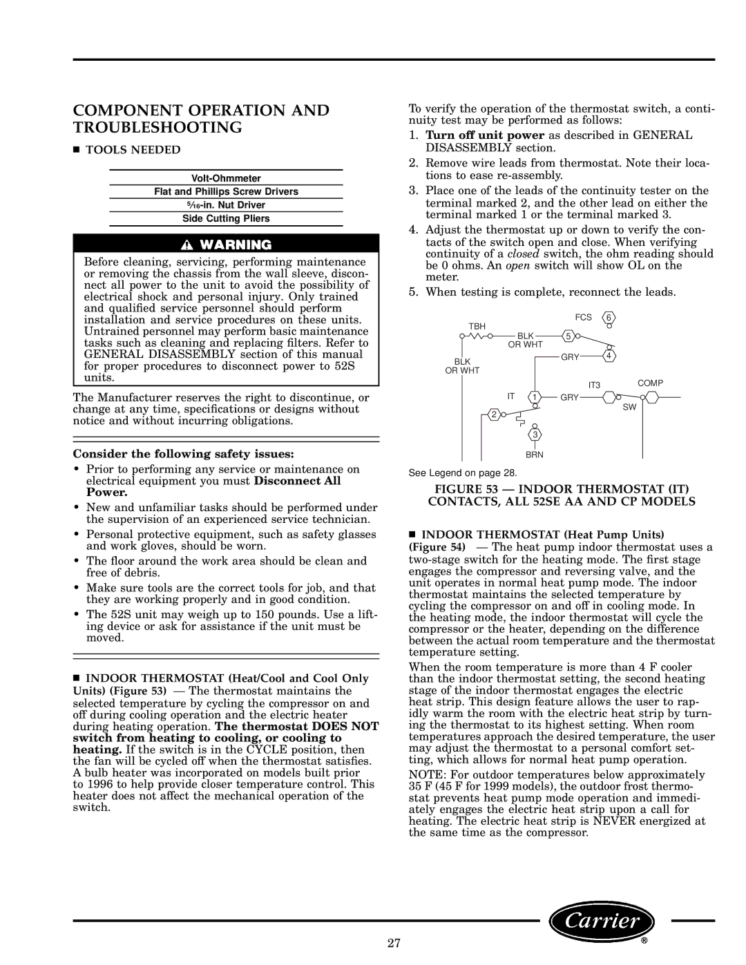
To verify the operation of the thermostat switch, a conti- nuity test may be performed as follows:
1.Turn off unit power as described in GENERAL DISASSEMBLY section.
2.Remove wire leads from thermostat. Note their loca- tions to ease
3.Place one of the leads of the continuity tester on the terminal marked 2, and the other lead on either the terminal marked 1 or the terminal marked 3.
4.Adjust the thermostat up or down to verify the con- tacts of the switch open and close. When verifying continuity of a closed switch, the ohm reading should be 0 ohms. An open switch will show OL on the meter.
5.When testing is complete, reconnect the leads.
TBH | FCS | 6 |
|
| |
BLK | 5 |
|
OR WHT |
|
|
BLK | GRY | 4 |
|
|
OR WHT
IT3 COMP
IT 1 GRY
SW
2
3
BRN
See Legend on page 28.
FIGURE 53 Ð INDOOR THERMOSTAT (IT) CONTACTS, ALL 52SE AA AND CP MODELS
INDOOR THERMOSTAT (Heat Pump Units)
(Figure 54) Ð The heat pump indoor thermostat uses a two-stage switch for the heating mode. The ®rst stage engages the compressor and reversing valve, and the unit operates in normal heat pump mode. The indoor thermostat maintains the selected temperature by cycling the compressor on and off in cooling mode. In the heating mode, the indoor thermostat will cycle the compressor or the heater, depending on the difference between the actual room temperature and the thermostat temperature setting.
When the room temperature is more than 4 F cooler than the indoor thermostat setting, the second heating stage of the indoor thermostat engages the electric heat strip. This design feature allows the user to rap- idly warm the room with the electric heat strip by turn- ing the thermostat to its highest setting. When room temperatures approach the desired temperature, the user may adjust the thermostat to a personal comfort set- ting, which allows for normal heat pump operation.
NOTE: For outdoor temperatures below approximately 35 F (45 F for 1999 models), the outdoor frost thermo- stat prevents heat pump mode operation and immedi- ately engages the electric heat strip upon a call for heating. The electric heat strip is NEVER energized at the same time as the compressor.
27