52S
SERIES
REMOVING THE COMPRESSOR Ð Follow the steps
below to remove the compressor:
1.Disconnect all power to unit.
2.Remove unit from wall sleeve as detailed in the GENERAL DISASSEMBLY section. The unit weighs up to 150 pounds. Seek assistance or use a lifting device when removing unit from wall sleeve.
3.If the unit is a heat pump: Disconnect the wire plug on the reversing valve solenoid and carefully remove the outdoor thermostat capillary from the outdoor coil.
4.Attach the piercing valve to the suction side pro- cess tube below the crimps. Attach Carrier TOTALTEST kit (Part No.
5.When all the refrigerant has been recovered, re- move the terminal cover from the compressor with a nut driver. Disconnect the 3 wires from the compressor and label the location of each. Once the wires are labeled, replace the terminal cover to protect the compressor terminals.
6.Remove the air system assembly by following the procedure detailed in the SEASONAL CLEANING section under Accessing the Indoor and Out- door Coils.
7.Remove the piercing valve and cut the crimped por- tion of both process tubes off with a small tubing cutter. Braze a Parker access valve on each process tube. Using a torch, disconnect the suction and discharge tubes from the compressor connections.
8.Remove the compressor mounting bolts, and remove the compressor.
The compressor may still be hot from the brazing process.
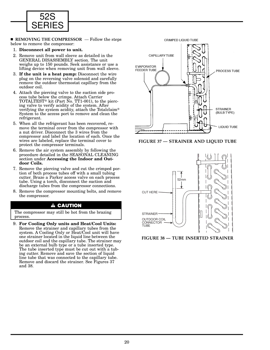
9.For Cooling Only units and Heat/Cool Units: Remove the strainer and capillary tubes from the system. A Cooling Only or Heat/Cool unit will have one strainer located in the liquid line between the outdoor coil and the capillary tube. The strainer may be an external bulb type or a tube inserted type. The tube inserted type must be cut out with a tub- ing cutter. Remove and save the section of liquid line tube that was connected to the capillary tube. Remove and discard the strainer. See Figures 37 and 38.
FIGURE 37 Ð STRAINER AND LIQUID TUBE
52mm
CUT HERE ![]()
STRAINER ![]()
OUTDOOR COIL
CONNECTOR
TUBE
FIGURE 38 Ð TUBE INSERTED STRAINER
20