52S
SERIES
HEATERS
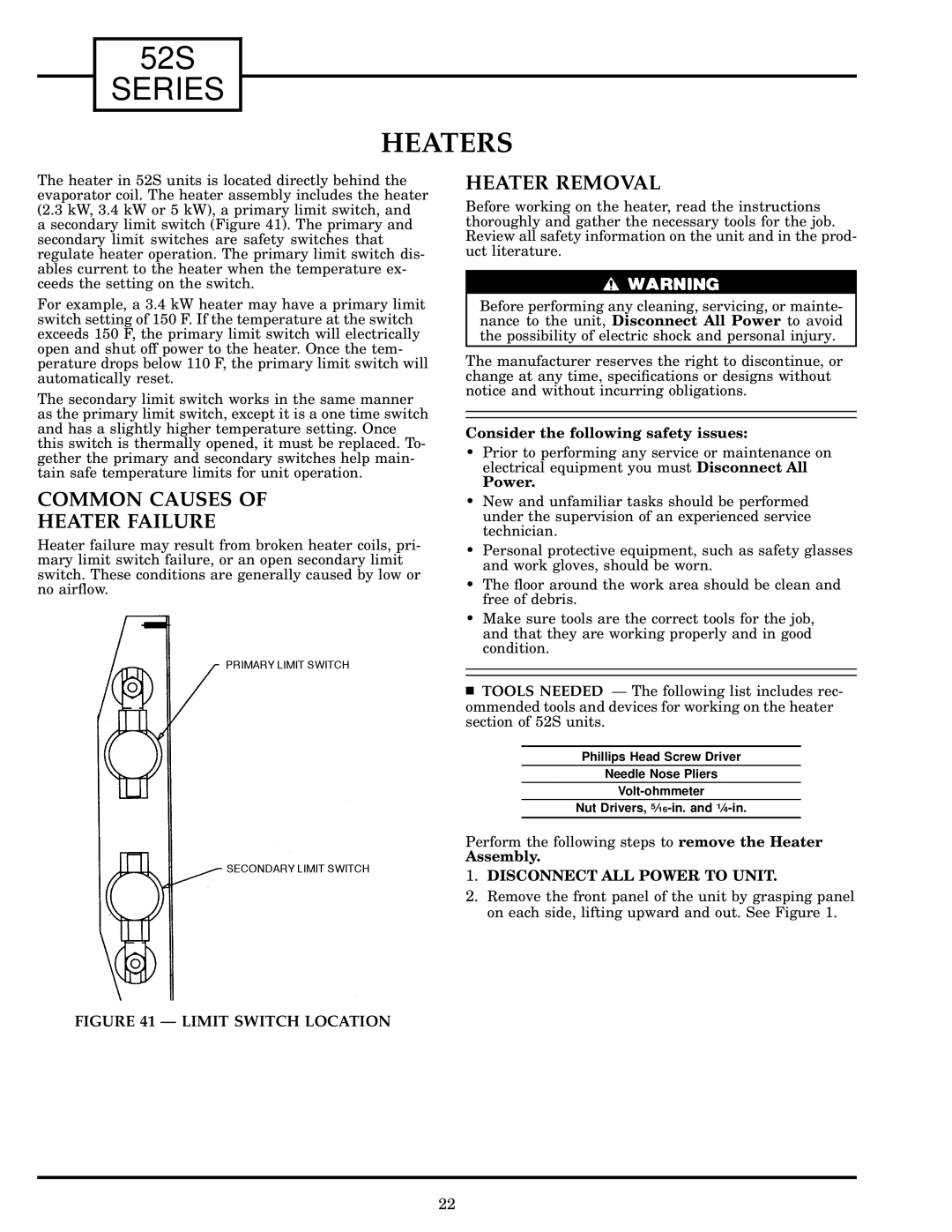
The heater in 52S units is located directly behind the evaporator coil. The heater assembly includes the heater (2.3 kW, 3.4 kW or 5 kW), a primary limit switch, and a secondary limit switch (Figure 41). The primary and secondary limit switches are safety switches that regulate heater operation. The primary limit switch dis- ables current to the heater when the temperature ex- ceeds the setting on the switch.
For example, a 3.4 kW heater may have a primary limit switch setting of 150 F. If the temperature at the switch exceeds 150 F, the primary limit switch will electrically open and shut off power to the heater. Once the tem- perature drops below 110 F, the primary limit switch will automatically reset.
The secondary limit switch works in the same manner as the primary limit switch, except it is a one time switch and has a slightly higher temperature setting. Once this switch is thermally opened, it must be replaced. To- gether the primary and secondary switches help main- tain safe temperature limits for unit operation.
COMMON CAUSES OF
HEATER FAILURE
Heater failure may result from broken heater coils, pri- mary limit switch failure, or an open secondary limit switch. These conditions are generally caused by low or no air¯ow.
HEATER REMOVAL
Before working on the heater, read the instructions thoroughly and gather the necessary tools for the job. Review all safety information on the unit and in the prod- uct literature.
Before performing any cleaning, servicing, or mainte- nance to the unit, Disconnect All Power to avoid the possibility of electric shock and personal injury.
The manufacturer reserves the right to discontinue, or change at any time, speci®cations or designs without notice and without incurring obligations.
Consider the following safety issues:
·Prior to performing any service or maintenance on electrical equipment you must Disconnect All
Power.
·New and unfamiliar tasks should be performed under the supervision of an experienced service technician.
·Personal protective equipment, such as safety glasses and work gloves, should be worn.
·The ¯oor around the work area should be clean and free of debris.
·Make sure tools are the correct tools for the job, and that they are working properly and in good condition.
TOOLS NEEDED Ð The following list includes rec- ommended tools and devices for working on the heater section of 52S units.
Phillips Head Screw Driver
Needle Nose Pliers
Nut Drivers,
Perform the following steps to remove the Heater
Assembly.
1.DISCONNECT ALL POWER TO UNIT.
2.Remove the front panel of the unit by grasping panel on each side, lifting upward and out. See Figure 1.
FIGURE 41 Ð LIMIT SWITCH LOCATION
22