3.Remove the unit from the sleeve as detailed in the GENERAL DISASSEMBLY section.
4.Remove the discharge air grille and the discharge air deck as detailed in the GENERAL DISASSEMBLY section. Save screws.
5.Once the air discharge deck is removed, the heater assembly is exposed. After noting positions of wires and labelling them, use a pair of needle nose pliers to carefully remove the wires connected to the heater assembly.
6.Remove the two
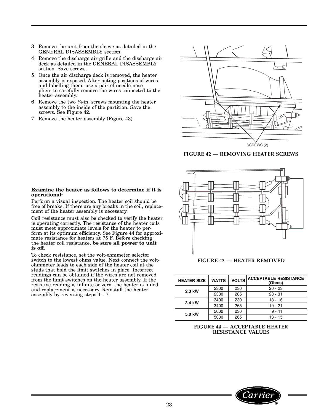
7.Remove the heater assembly (Figure 43).
Examine the heater as follows to determine if it is operational:
Perform a visual inspection. The heater coil should be free of breaks. If there are any breaks in the coil, replace- ment of the heater assembly is necessary.
Coil resistance must also be checked to verify the heater is operating correctly. The resistance of the heater coils must meet approximate levels for the heater to per- form at its optimum efficiency. See Figure 44 for approxi- mate resistance for heaters at 75 F. Before checking the heater coil resistance, be sure all power to unit is off.
To check resistance, set the
SCREWS (2)
FIGURE 42 Ð REMOVING HEATER SCREWS
FIGURE 43 Ð HEATER REMOVED
HEATER SIZE | WATTS | VOLTS | ACCEPTABLE RESISTANCE | |
|
|
| (Ohms) | |
2.3 kW | 2300 | 230 | 20 - 23 | |
2300 | 265 | 28 - 31 | ||
| ||||
3.4 kW | 3400 | 230 | 13 - 16 | |
3400 | 265 | 19 - 21 | ||
| ||||
5.0 kW | 5000 | 230 | 9 - 11 | |
5000 | 265 | 13 - 15 | ||
| ||||
|
|
|
|
FIGURE 44 Ð ACCEPTABLE HEATER
RESISTANCE VALUES
23