SECTION 6

SERVICE

NOTE

To avoid damage to the earth’s ozone layer, use a refrigerant recovery system whenever removing refrigerant. When working with refrigerants you must comply with all local government environmental laws. In the U.S.A., refer to EPA section 608.

WARNING

Never use air for leak testing. It has been de- termined that pressurized, mixtures of re- frigerant and air can undergo combustion when exposed to an ignition source.

6.1 SECTION LAYOUT

Service procedures are provided herein beginning with refrigeration system service, then refrigeration system component service, electrical system service, temperature recorder service and general service. Refer to the Table Of Contents to locate specific topics.

6.2 SERVICE VALVES

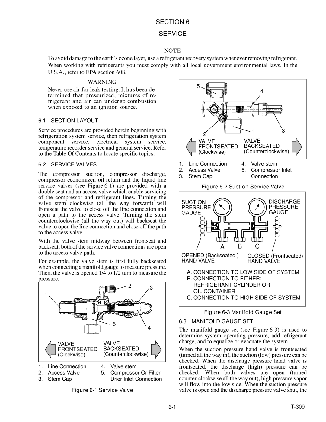
The compressor suction, compressor discharge, compressor economizer, oil return and the liquid line service valves (see Figure 6-1) are provided with a double seat and an access valve which enable servicing of the compressor and refrigerant lines. Turning the valve stem clockwise (all the way forward) will frontseat the valve to close off the line connection and open a path to the access valve. Turning the stem counterclockwise (all the way out) will backseat the valve to open the line connection and close off the path to the access valve.

With the valve stem midway between frontseat and backseat, both of the service valve connections are open to the access valve path.

For example, the valve stem is first fully backseated when connecting a manifold gauge to measure pressure. Then, the valve is opened 1/4 to 1/2 turn to measure the pressure.

2 3

1


5

4


VALVE

VALVE


FRONTSEATED

BACKSEATED


(Clockwise)

(Counterclockwise)

1.

Line Connection

4.

Valve stem

2.

Access Valve

5.

Compressor Or Filter

3.

Stem Cap


Drier Inlet Connection

Figure 6-1 Service Valve

5

4


2

1

3


VALVE

VALVE


FRONTSEATED

BACKSEATED


(Clockwise)

(Counterclockwise)

1.

Line Connection

4.

Valve stem

2.

Access Valve

5.

Compressor Inlet

3.

Stem Cap


Connection

Figure 6-2 Suction Service Valve

SUCTION

DISCHARGE

PRESSURE

PRESSURE

GAUGE

GAUGE

A

B

C

OPENED (Backseated )

CLOSED (Frontseated)

HAND VALVE


HAND VALVE

A. CONNECTION TO LOW SIDE OF SYSTEM B. CONNECTION TO EITHER:

REFRIGERANT CYLINDER OR OIL CONTAINER

C. CONNECTION TO HIGH SIDE OF SYSTEM

Figure 6-3 Manifold Gauge Set 6.3. MANIFOLD GAUGE SET

The manifold gauge set (see Figure 6-3) is used to determine system operating pressure, add refrigerant charge, and to equalize or evacuate the system.

When the suction pressure hand valve is frontseated (turned all the way in), the suction (low) pressure can be checked. When the discharge pressure hand valve is frontseated, the discharge (high) pressure can be checked. When both valves are open (turned counter-clockwise all the way out), high pressure vapor will flow into the low side. When the suction pressure valve is open and the discharge pressure valve shut, the

6-1

T-309

Page 65
Image 65
Carrier 69NT20-531-300 manual Section Service, Valve Frontseated Backseated

69NT20-531-300 specifications

The Carrier 69NT20-531-300 is a cutting-edge rooftop unit designed to meet the demanding requirements of commercial heating and cooling applications. This model embodies Carrier’s commitment to energy efficiency, reliability, and advanced technological features that enhance indoor comfort while minimizing operational costs.

One of the standout features of the Carrier 69NT20-531-300 is its high energy efficiency. It is equipped with advanced compressor technology that optimizes performance while reducing energy consumption. This ensures that businesses can maintain a comfortable indoor climate without incurring exorbitant utility bills. With a high Seasonal Energy Efficiency Ratio (SEER) and Energy Efficiency Ratio (EER), users can expect not only enhanced comfort but also significant cost savings over time.

The cooling capabilities of the 69NT20-531-300 are complemented by its robust heating options. This unit utilizes a gas heat exchanger, ensuring quick and even heating throughout the space. The combination of cooling and heating capabilities in one compact unit makes it a versatile choice for various applications, including retail spaces, offices, and warehouses.

In addition to its impressive performance specifications, the Carrier 69NT20-531-300 incorporates innovative technologies that further enhance its functionality. The unit comes with advanced controls, allowing for precise temperature regulation and zoning capabilities. This ensures that different areas of a building can maintain their desired temperatures based on usage, improving overall energy efficiency.

Durability is another hallmark of the Carrier 69NT20-531-300. The unit is constructed with high-quality materials and features a weather-proof cabinet that protects it from the elements, ensuring long-term reliability even in harsh conditions. Furthermore, its modular design simplifies maintenance, making it easy for technicians to access critical components.

The 69NT20-531-300 is also designed with low noise operation in mind. It employs sound-dampening technology to ensure that operations are quiet, making it an ideal choice for locations where noise reduction is a priority, such as schools or healthcare facilities.

Overall, the Carrier 69NT20-531-300 stands out as a premier choice for businesses looking for an efficient, reliable, and feature-rich rooftop HVAC unit. Its blend of energy efficiency, advanced technology, and durability positions it as a leader in commercial heating and cooling solutions, making it a valuable investment for any commercial property.