4.4CONNECT REMOTE MONITORING RECEPTACLE

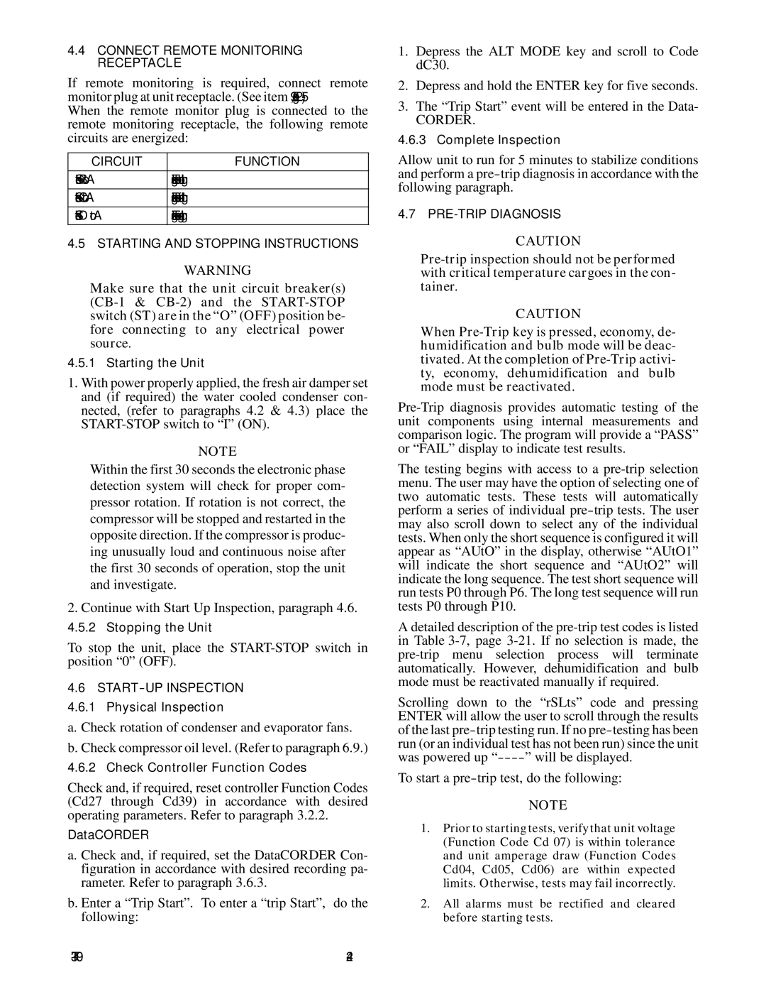
If remote monitoring is required, connect remote monitor plug at unit receptacle. (See item 9, Figure 2-5.)When the remote monitor plug is connected to the remote monitoring receptacle, the following remote circuits are energized:

CIRCUIT

FUNCTION

Sockets B to A

Energizes remote cool light


Sockets C to A

Energizes remote defrost light


Sockets D to A

Energizes remote in-range light


4.5 STARTING AND STOPPING INSTRUCTIONS

WARNING

Make sure that the unit circuit breaker(s) (CB-1 & CB-2) and the START-STOP switch (ST) are in the “O” (OFF) position be- fore connecting to any electrical power source.

4.5.1 Starting the Unit

1.With power properly applied, the fresh air damper set and (if required) the water cooled condenser con- nected, (refer to paragraphs 4.2 & 4.3) place the START-STOP switch to “I” (ON).

NOTE

Within the first 30 seconds the electronic phase detection system will check for proper com- pressor rotation. If rotation is not correct, the compressor will be stopped and restarted in the opposite direction. If the compressor is produc- ing unusually loud and continuous noise after the first 30 seconds of operation, stop the unit and investigate.

2.Continue with Start Up Inspection, paragraph 4.6.

4.5.2 Stopping the Unit

To stop the unit, place the START-STOP switch in position “0” (OFF).

4.6START--UP INSPECTION 4.6.1 Physical Inspection

a. Check rotation of condenser and evaporator fans. b. Check compressor oil level. (Refer to paragraph 6.9.)

4.6.2 Check Controller Function Codes

Check and, if required, reset controller Function Codes (Cd27 through Cd39) in accordance with desired operating parameters. Refer to paragraph 3.2.2.

DataCORDER

a. Check and, if required, set the DataCORDER Con- figuration in accordance with desired recording pa- rameter. Refer to paragraph 3.6.3.

b. Enter a “Trip Start”. To enter a “trip Start”, do the following:

1.Depress the ALT MODE key and scroll to Code dC30.

2.Depress and hold the ENTER key for five seconds.

3.The “Trip Start” event will be entered in the Data-

CORDER.

4.6.3 Complete Inspection

Allow unit to run for 5 minutes to stabilize conditions and perform a pre-trip diagnosis in accordance with the following paragraph.

4.7 PRE-TRIP DIAGNOSIS

CAUTION

Pre-trip inspection should not be performed with critical temperature cargoes in the con- tainer.

CAUTION

When Pre-Trip key is pressed, economy, de- humidification and bulb mode will be deac- tivated. At the completion of Pre-Trip activi- ty, economy, dehumidification and bulb mode must be reactivated.

Pre-Trip diagnosis provides automatic testing of the unit components using internal measurements and comparison logic. The program will provide a “PASS” or “FAIL” display to indicate test results.

The testing begins with access to a pre-trip selection menu. The user may have the option of selecting one of two automatic tests. These tests will automatically perform a series of individual pre-trip tests. The user may also scroll down to select any of the individual tests. When only the short sequence is configured it will appear as “AUtO” in the display, otherwise “AUtO1” will indicate the short sequence and “AUtO2” will indicate the long sequence. The test short sequence will run tests P0 through P6. The long test sequence will run tests P0 through P10.

A detailed description of the pre-trip test codes is listed in Table 3-7, page 3-21. If no selection is made, the pre-trip menu selection process will terminate automatically. However, dehumidification and bulb mode must be reactivated manually if required.

Scrolling down to the “rSLts” code and pressing ENTER will allow the user to scroll through the results of the last pre-trip testing run. If no pre-testing has been run (or an individual test has not been run) since the unit

was powered up “------

” will be displayed.

To start a pre-trip test, do the following:

NOTE

1.Prior to starting tests, verify that unit voltage (Function Code Cd 07) is within tolerance and unit amperage draw (Function Codes Cd04, Cd05, Cd06) are within expected limits. Otherwise, tests may fail incorrectly.

2.All alarms must be rectified and cleared before starting tests.

T-309

4-2

Page 54
Image 54
Carrier 69NT20-531-300 manual Will be displayed, To start a pre-trip test, do the following

69NT20-531-300 specifications

The Carrier 69NT20-531-300 is a cutting-edge rooftop unit designed to meet the demanding requirements of commercial heating and cooling applications. This model embodies Carrier’s commitment to energy efficiency, reliability, and advanced technological features that enhance indoor comfort while minimizing operational costs.

One of the standout features of the Carrier 69NT20-531-300 is its high energy efficiency. It is equipped with advanced compressor technology that optimizes performance while reducing energy consumption. This ensures that businesses can maintain a comfortable indoor climate without incurring exorbitant utility bills. With a high Seasonal Energy Efficiency Ratio (SEER) and Energy Efficiency Ratio (EER), users can expect not only enhanced comfort but also significant cost savings over time.

The cooling capabilities of the 69NT20-531-300 are complemented by its robust heating options. This unit utilizes a gas heat exchanger, ensuring quick and even heating throughout the space. The combination of cooling and heating capabilities in one compact unit makes it a versatile choice for various applications, including retail spaces, offices, and warehouses.

In addition to its impressive performance specifications, the Carrier 69NT20-531-300 incorporates innovative technologies that further enhance its functionality. The unit comes with advanced controls, allowing for precise temperature regulation and zoning capabilities. This ensures that different areas of a building can maintain their desired temperatures based on usage, improving overall energy efficiency.

Durability is another hallmark of the Carrier 69NT20-531-300. The unit is constructed with high-quality materials and features a weather-proof cabinet that protects it from the elements, ensuring long-term reliability even in harsh conditions. Furthermore, its modular design simplifies maintenance, making it easy for technicians to access critical components.

The 69NT20-531-300 is also designed with low noise operation in mind. It employs sound-dampening technology to ensure that operations are quiet, making it an ideal choice for locations where noise reduction is a priority, such as schools or healthcare facilities.

Overall, the Carrier 69NT20-531-300 stands out as a premier choice for businesses looking for an efficient, reliable, and feature-rich rooftop HVAC unit. Its blend of energy efficiency, advanced technology, and durability positions it as a leader in commercial heating and cooling solutions, making it a valuable investment for any commercial property.