Carrier 69NT20-531-300 manual Condenser FAN and Motor Assembly

Models: 69NT20-531-300

1 93
Download 93 pages 33.37 Kb
Page 72
Image 72

6.10.2 Checking High Pressure Switch

WARNING

Do not use a nitrogen cylinder without a pressure regulator. Do not use oxygen in or near a refrigeration system as an explosion may occur.

NOTE

The high pressure switch is non-adjustable.

a. Remove switch as outlined in paragraph 6.10.1

b. Connect ohmmeter or continuity light across switch terminals. Ohm meter will indicate no resistance or continuity light will be illuminated if the switch closed after relieving compressor pressure.

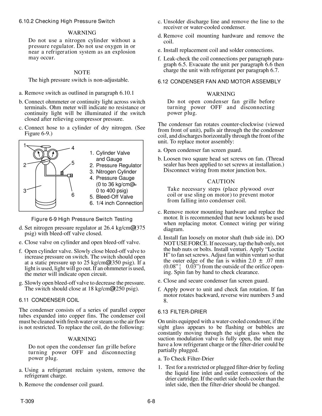
c. Connect hose to a cylinder of dry nitrogen. (See Figure 6-9.)

c. Unsolder discharge line and remove the line to the receiver or water-cooled condenser.

d. Remove coil mounting hardware and remove the coil.

e. Install replacement coil and solder connections.

f.Leak-check the coil connections per paragraph para- graph 6.5. Evacuate the unit per paragraph 6.6 then charge the unit with refrigerant per paragraph 6.7.

6.12 CONDENSER FAN AND MOTOR ASSEMBLY

WARNING

Do not open condenser fan grille before turning power OFF and disconnecting power plug.

The condenser fan rotates counter-clockwise (viewed from front of unit), pulls air through the the condenser coil, and discharges horizontally through the front of the unit. To replace motor assembly:

1

2

3

4

5

6

1.Cylinder Valve and Gauge

2.Pressure Regulator

3.Nitrogen Cylinder

4.Pressure Gauge (0 to 36 kg/cm@ = 0 to 400 psig)

5.Bleed-Off Valve

6.1/4 inch Connection

a. Open condenser fan screen guard.

b. Loosen two square head set screws on fan. (Thread sealer has been applied to set screws at installation.) Disconnect wiring from motor junction box.

CAUTION

Take necessary steps (place plywood over coil or use sling on motor) to prevent motor from falling into condenser coil.

Figure 6-9 High Pressure Switch Testing

d. Set nitrogen pressure regulator at 26.4 kg/cm@ (375 psig) with bleed-off valve closed.

e. Close valve on cylinder and open bleed-off valve.

f.Open cylinder valve. Slowly close bleed-off valve to increase pressure on switch. The switch should open at a static pressure up to 25 kg/cm@ (350 psig). If a light is used, light will go out. If an ohmmeter is used, the meter will indicate open circuit.

g.Slowly open bleed-off valve to decrease the pressure. The switch should close at 18 kg/cm@ (250 psig).

6.11 CONDENSER COIL

The condenser consists of a series of parallel copper tubes expanded into copper fins. The condenser coil must be cleaned with fresh water or steam so the air flow is not restricted. To replace the coil, do the following:

WARNING

Do not open the condenser fan grille before turning power OFF and disconnecting power plug.

a. Using a refrigerant reclaim system, remove the refrigerant charge.

b. Remove the condenser coil guard.

c. Remove motor mounting hardware and replace the motor. It is recommended that new locknuts be used when replacing motor. Connect wiring per wiring diagram.

d. Install fan loosely on motor shaft (hub side in). DO NOT USE FORCE. If necessary, tap the hub only, not the hub nuts or bolts. Install venturi. Apply “Loctite H” to fan set screws. Adjust fan within venturi so that the outer edge of the fan is within 2.0 ± .07 mm (0.08” ¦ 0.03”) from the outside of the orifice open- ing. Spin fan by hand to check clearance.

e. Close and secure condenser fan screen guard.

f. Apply power to unit and check fan rotation. If fan motor rotates backward, reverse wire numbers 5 and 8.

6.13 FILTER-DRIER

On units equipped with a water-cooled condenser, if the sight glass appears to be flashing or bubbles are constantly moving through the sight glass when the suction modulation valve is fully open, the unit may have a low refrigerant charge or the filter-drier could be partially plugged.

a. To Check Filter-Drier

1.Test for a restricted or plugged filter-drier by feeling the liquid line inlet and outlet connections of the drier cartridge. If the outlet side feels cooler than the inlet side, then the filter-drier should be changed.

T-309

6-8

Page 72
Image 72
Carrier 69NT20-531-300 manual Condenser FAN and Motor Assembly

69NT20-531-300 specifications

The Carrier 69NT20-531-300 is a cutting-edge rooftop unit designed to meet the demanding requirements of commercial heating and cooling applications. This model embodies Carrier’s commitment to energy efficiency, reliability, and advanced technological features that enhance indoor comfort while minimizing operational costs.

One of the standout features of the Carrier 69NT20-531-300 is its high energy efficiency. It is equipped with advanced compressor technology that optimizes performance while reducing energy consumption. This ensures that businesses can maintain a comfortable indoor climate without incurring exorbitant utility bills. With a high Seasonal Energy Efficiency Ratio (SEER) and Energy Efficiency Ratio (EER), users can expect not only enhanced comfort but also significant cost savings over time.

The cooling capabilities of the 69NT20-531-300 are complemented by its robust heating options. This unit utilizes a gas heat exchanger, ensuring quick and even heating throughout the space. The combination of cooling and heating capabilities in one compact unit makes it a versatile choice for various applications, including retail spaces, offices, and warehouses.

In addition to its impressive performance specifications, the Carrier 69NT20-531-300 incorporates innovative technologies that further enhance its functionality. The unit comes with advanced controls, allowing for precise temperature regulation and zoning capabilities. This ensures that different areas of a building can maintain their desired temperatures based on usage, improving overall energy efficiency.

Durability is another hallmark of the Carrier 69NT20-531-300. The unit is constructed with high-quality materials and features a weather-proof cabinet that protects it from the elements, ensuring long-term reliability even in harsh conditions. Furthermore, its modular design simplifies maintenance, making it easy for technicians to access critical components.

The 69NT20-531-300 is also designed with low noise operation in mind. It employs sound-dampening technology to ensure that operations are quiet, making it an ideal choice for locations where noise reduction is a priority, such as schools or healthcare facilities.

Overall, the Carrier 69NT20-531-300 stands out as a premier choice for businesses looking for an efficient, reliable, and feature-rich rooftop HVAC unit. Its blend of energy efficiency, advanced technology, and durability positions it as a leader in commercial heating and cooling solutions, making it a valuable investment for any commercial property.