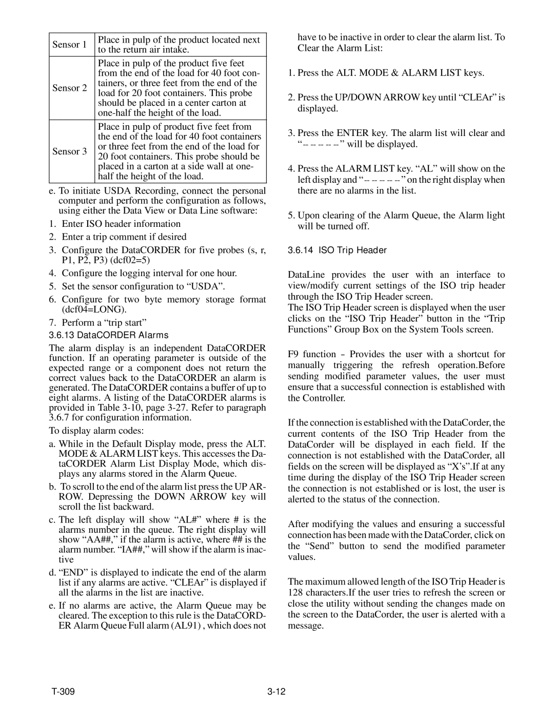
Sensor 1

Place in pulp of the product located next

to the return air intake.


Place in pulp of the product five feet


from the end of the load for 40 foot con-

Sensor 2

tainers, or three feet from the end of the

load for 20 foot containers. This probe


should be placed in a center carton at


one-half the height of the load.


Place in pulp of product five feet from


the end of the load for 40 foot containers

Sensor 3

or three feet from the end of the load for

20 foot containers. This probe should be


placed in a carton at a side wall at one-


half the height of the load.

e. To initiate USDA Recording, connect the personal computer and perform the configuration as follows, using either the Data View or Data Line software:

1.Enter ISO header information

2.Enter a trip comment if desired

3.Configure the DataCORDER for five probes (s, r, P1, P2, P3) (dcf02=5)

4.Configure the logging interval for one hour.

5.Set the sensor configuration to “USDA”.

6.Configure for two byte memory storage format (dcf04=LONG).

7.Perform a “trip start”

3.6.13 DataCORDER Alarms

The alarm display is an independent DataCORDER function. If an operating parameter is outside of the expected range or a component does not return the correct values back to the DataCORDER an alarm is generated. The DataCORDER contains a buffer of up to eight alarms. A listing of the DataCORDER alarms is provided in Table 3-10, page 3-27. Refer to paragraph

3.6.7for configuration information. To display alarm codes:

a. While in the Default Display mode, press the ALT. MODE & ALARM LIST keys. This accesses the Da- taCORDER Alarm List Display Mode, which dis- plays any alarms stored in the Alarm Queue.

b.To scroll to the end of the alarm list press the UP AR- ROW. Depressing the DOWN ARROW key will scroll the list backward.

c.The left display will show “AL#” where # is the alarms number in the queue. The right display will show “AA##,” if the alarm is active, where ## is the alarm number. “IA##,” will show if the alarm is inac- tive

d.“END” is displayed to indicate the end of the alarm list if any alarms are active. “CLEAr” is displayed if all the alarms in the list are inactive.

e.If no alarms are active, the Alarm Queue may be cleared. The exception to this rule is the DataCORD- ER Alarm Queue Full alarm (AL91) , which does not

have to be inactive in order to clear the alarm list. To Clear the Alarm List:

1.Press the ALT. MODE & ALARM LIST keys.

2.Press the UP/DOWN ARROW key until “CLEAr” is displayed.

3.Press the ENTER key. The alarm list will clear and ----------” will be displayed.

4.Press the ALARM LIST key. “AL” will show on the left display and ----------” on the right display when there are no alarms in the list.

5.Upon clearing of the Alarm Queue, the Alarm light will be turned off.

3.6.14 ISO Trip Header

DataLine provides the user with an interface to view/modify current settings of the ISO trip header through the ISO Trip Header screen.

The ISO Trip Header screen is displayed when the user clicks on the “ISO Trip Header” button in the “Trip Functions” Group Box on the System Tools screen.

F9 function - Provides the user with a shortcut for manually triggering the refresh operation.Before sending modified parameter values, the user must ensure that a successful connection is established with the Controller.

If the connection is established with the DataCorder, the current contents of the ISO Trip Header from the DataCorder will be displayed in each field. If the connection is not established with the DataCorder, all fields on the screen will be displayed as “X’s”.If at any time during the display of the ISO Trip Header screen the connection is not established or is lost, the user is alerted to the status of the connection.

After modifying the values and ensuring a successful connection has been made with the DataCorder, click on the “Send” button to send the modified parameter values.

The maximum allowed length of the ISO Trip Header is 128 characters.If the user tries to refresh the screen or close the utility without sending the changes made on the screen to the DataCorder, the user is alerted with a message.

T-309

3-12

Page 37
Image 37
Carrier 69NT20-531-300 manual DataCORDER Alarms

69NT20-531-300 specifications

The Carrier 69NT20-531-300 is a cutting-edge rooftop unit designed to meet the demanding requirements of commercial heating and cooling applications. This model embodies Carrier’s commitment to energy efficiency, reliability, and advanced technological features that enhance indoor comfort while minimizing operational costs.

One of the standout features of the Carrier 69NT20-531-300 is its high energy efficiency. It is equipped with advanced compressor technology that optimizes performance while reducing energy consumption. This ensures that businesses can maintain a comfortable indoor climate without incurring exorbitant utility bills. With a high Seasonal Energy Efficiency Ratio (SEER) and Energy Efficiency Ratio (EER), users can expect not only enhanced comfort but also significant cost savings over time.

The cooling capabilities of the 69NT20-531-300 are complemented by its robust heating options. This unit utilizes a gas heat exchanger, ensuring quick and even heating throughout the space. The combination of cooling and heating capabilities in one compact unit makes it a versatile choice for various applications, including retail spaces, offices, and warehouses.

In addition to its impressive performance specifications, the Carrier 69NT20-531-300 incorporates innovative technologies that further enhance its functionality. The unit comes with advanced controls, allowing for precise temperature regulation and zoning capabilities. This ensures that different areas of a building can maintain their desired temperatures based on usage, improving overall energy efficiency.

Durability is another hallmark of the Carrier 69NT20-531-300. The unit is constructed with high-quality materials and features a weather-proof cabinet that protects it from the elements, ensuring long-term reliability even in harsh conditions. Furthermore, its modular design simplifies maintenance, making it easy for technicians to access critical components.

The 69NT20-531-300 is also designed with low noise operation in mind. It employs sound-dampening technology to ensure that operations are quiet, making it an ideal choice for locations where noise reduction is a priority, such as schools or healthcare facilities.

Overall, the Carrier 69NT20-531-300 stands out as a premier choice for businesses looking for an efficient, reliable, and feature-rich rooftop HVAC unit. Its blend of energy efficiency, advanced technology, and durability positions it as a leader in commercial heating and cooling solutions, making it a valuable investment for any commercial property.