1

2

3

2

5


4

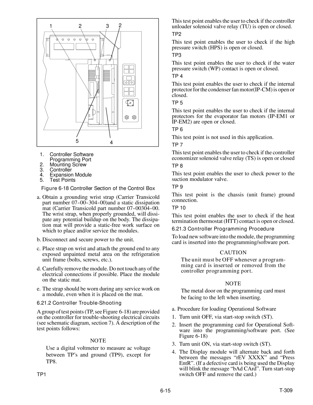
1.Controller Software Programming Port

2.Mounting Screw

3.Controller

4.Expansion Module

5.Test Points

Figure 6-18 Controller Section of the Control Box

a. Obtain a grounding wrist strap (Carrier Transicold part number 07-00-304-00)and a static dissipation mat (Carrier Transicold part number 07-00304-00. The wrist strap, when properly grounded, will dissi- pate any potential buildup on the body. The dissipa- tion mat will provide a static-free work surface on which to place and/or service the modules.

b. Disconnect and secure power to the unit.

c.Place strap on wrist and attach the ground end to any exposed unpainted metal area on the refrigeration unit frame (bolts, screws, etc.).

d.Carefully remove the module. Do not touch any of the electrical connections if possible. Place the module on the static mat.

e.The strap should be worn during any service work on a module, even when it is placed on the mat.

6.21.2 Controller Trouble-Shooting

A group of test points (TP, see Figure 6-18) are provided on the controller for trouble-shooting electrical circuits (see schematic diagram, section 7). A description of the test points follows:

NOTE

Use a digital voltmeter to measure ac voltage between TP’s and ground (TP9), except for TP8.

TP1

This test point enables the user to check if the controller unloader solenoid valve relay (TU) is open or closed.

TP2

This test point enables the user to check if the high pressure switch (HPS) is open or closed.

TP3

This test point enables the user to check if the water pressure switch (WP) contact is open or closed.

TP 4

This test point enables the user to check if the internal protector for the condenser fan motor(IP-CM) is open or closed.

TP 5

This test point enables the user to check if the internal protectors for the evaporator fan motors (IP-EM1 or IP-EM2) are open or closed.

TP 6

This test point is not used in this application.

TP 7

This test point enables the user to check if the controller economizer solenoid valve relay (TS) is open or closed

TP 8

This test point enables the user to check power to the suction modulator valve.

TP 9

This test point is the chassis (unit frame) ground connection.

TP 10

This test point enables the user to check if the heat termination thermostat (HTT) contact is open or closed.

6.21.3 Controller Programming Procedure

To load new software into the module, the programming card is inserted into the programming/software port.

CAUTION

The unit must be OFF whenever a program- ming card is inserted or removed from the controller programming port.

NOTE

The metal door on the programming card must be facing to the left when inserting.

a. Procedure for loading Operational Software

1.Turn unit OFF, via start-stop switch (ST).

2.Insert the programming card for Operational Soft- ware into the programming/software port. (See Figure 6-18)

3.Turn unit ON, via start-stop switch (ST).

4.The Display module will alternate back and forth between the messages “rEV XXXX” and “Press EntR”. (If a defective card is being used the Display will blink the message “bAd CArd”. Turn start-stop switch OFF and remove the card.)

6-15

T-309

Page 79
Image 79
Carrier 69NT20-531-300 manual TP1

69NT20-531-300 specifications

The Carrier 69NT20-531-300 is a cutting-edge rooftop unit designed to meet the demanding requirements of commercial heating and cooling applications. This model embodies Carrier’s commitment to energy efficiency, reliability, and advanced technological features that enhance indoor comfort while minimizing operational costs.

One of the standout features of the Carrier 69NT20-531-300 is its high energy efficiency. It is equipped with advanced compressor technology that optimizes performance while reducing energy consumption. This ensures that businesses can maintain a comfortable indoor climate without incurring exorbitant utility bills. With a high Seasonal Energy Efficiency Ratio (SEER) and Energy Efficiency Ratio (EER), users can expect not only enhanced comfort but also significant cost savings over time.

The cooling capabilities of the 69NT20-531-300 are complemented by its robust heating options. This unit utilizes a gas heat exchanger, ensuring quick and even heating throughout the space. The combination of cooling and heating capabilities in one compact unit makes it a versatile choice for various applications, including retail spaces, offices, and warehouses.

In addition to its impressive performance specifications, the Carrier 69NT20-531-300 incorporates innovative technologies that further enhance its functionality. The unit comes with advanced controls, allowing for precise temperature regulation and zoning capabilities. This ensures that different areas of a building can maintain their desired temperatures based on usage, improving overall energy efficiency.

Durability is another hallmark of the Carrier 69NT20-531-300. The unit is constructed with high-quality materials and features a weather-proof cabinet that protects it from the elements, ensuring long-term reliability even in harsh conditions. Furthermore, its modular design simplifies maintenance, making it easy for technicians to access critical components.

The 69NT20-531-300 is also designed with low noise operation in mind. It employs sound-dampening technology to ensure that operations are quiet, making it an ideal choice for locations where noise reduction is a priority, such as schools or healthcare facilities.

Overall, the Carrier 69NT20-531-300 stands out as a premier choice for businesses looking for an efficient, reliable, and feature-rich rooftop HVAC unit. Its blend of energy efficiency, advanced technology, and durability positions it as a leader in commercial heating and cooling solutions, making it a valuable investment for any commercial property.