Table 6-1 Compressor Kit


Item

Component

Qty

1

Compressor

1

2

Service Valve Seal

3

3

Mylar Washers

4

4

Wire Tie

2

5

Oil Sight Glass Plug

1

6

Resilient Mount

4

7

Upper Shock Mount Ring

1

8

Upper Shock Mount Bushing

1

9

Compressor Power Plug O-Ring

1

10

SST Washers

8

c. If the compressor is not operational, turn the unit start-stop switch (ST) and unit circuit breaker (CB-1) OFF. Disconnect power to the unit and front- seat the discharge, suction, economizer, and oil return service valves.

Remove all remaining refrigerant from the compres- sor using a refrigerant recovery system. Connect hoses to suction, economizer and discharge service valves ports. Evacuate compressor to 500 microns (75.9 cm Hg vacuum = 29.9 inches Hg vacuum).

d. Make sure power to the unit is OFF and unit power plug disconnected. Disconnect the power plug from the compressor.

e.Loosen and break the seal at fittings from the suction, discharge, economizer, and the oil return service valves. Remove fittings and discard service valve seals, retain oil return valve O-ring.

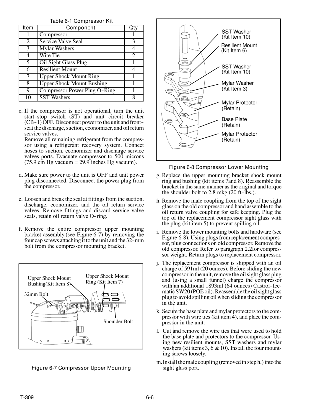
f.Remove the entire compressor upper mounting bracket assembly,(see Figure 6-7) by removing the four cap screws attaching it to the unit and the 32-mm bolt from the compressor mounting bracket.

Upper Shock Mount

Upper Shock Mount

Ring (Kit Item 7)

Bushing(Kit Item 8)


32mm Bolt


Shoulder Bolt

Figure 6-7 Compressor Upper Mounting

SST Washer

(Kit Item 10)

Resilient Mount

(Kit Item 6)

SST Washer

(Kit Item 10)

Mylar Washer

(Kit Item 3)

Mylar Protector (Retain)

Base Plate (Retain)

Mylar Protector (Retain)

Figure 6-8 Compressor Lower Mounting

g. Replace the upper mounting bracket shock mount ring and bushing (kit items 7and 8). Reassemble the bracket in the same manner as the original and torque the shoulder bolt to 2.8 mkg (20 ft-lbs.).

h. Remove the male coupling from the top of the sight glass on the old compressor and hand assemble to the oil return valve coupling for safe keeping. Plug the top of the replacement compressor sight glass with the plug (kit item 5) to prevent spilling oil.

i.Remove the lower mounting bolts and hardware (see Figure 6-8). Using plugs from replacement compres- sor, plug connections on old compressor. Remove the old compressor. Refer to paragraph 2.2for compres- sor weight. Return plugs to replacement compressor.

j.The replacement compressor is shipped with an oil charge of 591ml (20 ounces). Before sliding the new compressor in the unit, remove the oil sight glass plug and (using a small funnel) charge the compressor with an additional 1893ml (64 ounces) Castrol-Ice- matic SW20 (POE oil). Reassemble the oil sight glass plug to avoid spilling oil when sliding the compressor in the unit.

k.Secure the base plate and mylar protectors to the com- pressor with wire ties (kit item 4), and place the com- pressor in the unit.

l.Cut and remove the wire ties that were used to hold the base plate and protectors to the compressor. Us- ing new resilient mounts, SST washers and mylar washers (kit items 3, 6 & 10). Install the four mount- ing screws loosely.

m.Install the male coupling (removed in step h.) into the sight glass port.

T-309

6-6

Page 70
Image 70
Carrier 69NT20-531-300 manual Compressor Upper Mounting

69NT20-531-300 specifications

The Carrier 69NT20-531-300 is a cutting-edge rooftop unit designed to meet the demanding requirements of commercial heating and cooling applications. This model embodies Carrier’s commitment to energy efficiency, reliability, and advanced technological features that enhance indoor comfort while minimizing operational costs.

One of the standout features of the Carrier 69NT20-531-300 is its high energy efficiency. It is equipped with advanced compressor technology that optimizes performance while reducing energy consumption. This ensures that businesses can maintain a comfortable indoor climate without incurring exorbitant utility bills. With a high Seasonal Energy Efficiency Ratio (SEER) and Energy Efficiency Ratio (EER), users can expect not only enhanced comfort but also significant cost savings over time.

The cooling capabilities of the 69NT20-531-300 are complemented by its robust heating options. This unit utilizes a gas heat exchanger, ensuring quick and even heating throughout the space. The combination of cooling and heating capabilities in one compact unit makes it a versatile choice for various applications, including retail spaces, offices, and warehouses.

In addition to its impressive performance specifications, the Carrier 69NT20-531-300 incorporates innovative technologies that further enhance its functionality. The unit comes with advanced controls, allowing for precise temperature regulation and zoning capabilities. This ensures that different areas of a building can maintain their desired temperatures based on usage, improving overall energy efficiency.

Durability is another hallmark of the Carrier 69NT20-531-300. The unit is constructed with high-quality materials and features a weather-proof cabinet that protects it from the elements, ensuring long-term reliability even in harsh conditions. Furthermore, its modular design simplifies maintenance, making it easy for technicians to access critical components.

The 69NT20-531-300 is also designed with low noise operation in mind. It employs sound-dampening technology to ensure that operations are quiet, making it an ideal choice for locations where noise reduction is a priority, such as schools or healthcare facilities.

Overall, the Carrier 69NT20-531-300 stands out as a premier choice for businesses looking for an efficient, reliable, and feature-rich rooftop HVAC unit. Its blend of energy efficiency, advanced technology, and durability positions it as a leader in commercial heating and cooling solutions, making it a valuable investment for any commercial property.