Carrier 69NT20-531-300 manual Refrigeration Circuit 2.5.1 Standard Operation

Models: 69NT20-531-300

1 93
Download 93 pages 33.37 Kb
Page 23
Image 23

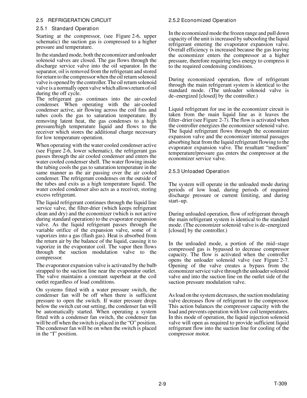
2.5 REFRIGERATION CIRCUIT 2.5.1 Standard Operation

Starting at the compressor, (see Figure 2-6, upper schematic) the suction gas is compressed to a higher pressure and temperature.

In the standard mode, both the economizer and unloader solenoid valves are closed. The gas flows through the discharge service valve into the oil separator. In the separator, oil is removed from the refrigerant and stored for return to the compressor when the oil return solenoid valve is opened by the controller. The oil return solenoid valve is a normally open valve which allows return of oil during the off cycle.

The refrigerant gas continues into the air-cooled condenser. When operating with the air-cooled condenser active, air flowing across the coil fins and tubes cools the gas to saturation temperature. By removing latent heat, the gas condenses to a high pressure/high temperature liquid and flows to the receiver which stores the additional charge necessary for low temperature operation.

When operating with the water cooled condenser active (see Figure 2-6, lower schematic), the refrigerant gas passes through the air cooled condenser and enters the water cooled condenser shell. The water flowing inside the tubing cools the gas to saturation temperature in the same manner as the air passing over the air cooled condenser. The refrigerant condenses on the outside of the tubes and exits as a high temperature liquid. The water cooled condenser also acts as a receiver, storing excess refrigerant.

The liquid refrigerant continues through the liquid line service valve, the filter-drier (which keeps refrigerant clean and dry) and the economizer (which is not active during standard operation) to the evaporator expansion valve. As the liquid refrigerant passes through the variable orifice of the expansion valve, some of it vaporizes into a gas (flash gas). Heat is absorbed from the return air by the balance of the liquid, causing it to vaporize in the evaporator coil. The vapor then flows through the suction modulation valve to the compressor.

The evaporator expansion valve is activated by the bulb strapped to the suction line near the evaporator outlet. The valve maintains a constant superheat at the coil outlet regardless of load conditions.

On systems fitted with a water pressure switch, the condenser fan will be off when there is sufficient pressure to open the switch. If water pressure drops below the switch cut out setting, the condenser fan will be automatically started. When operating a system fitted with a condenser fan switch, the condenser fan will be off when the switch is placed in the “O” position. The condenser fan will be on when the switch is placed in the “I” position.

2.5.2 Economized Operation

In the economized mode the frozen range and pull down capacity of the unit is increased by subcooling the liquid refrigerant entering the evaporator expansion valve. Overall efficiency is increased because the gas leaving the economizer enters the compressor at a higher pressure, therefore requiring less energy to compress it to the required condensing conditions.

During economized operation, flow of refrigerant through the main refrigerant system is identical to the standard mode. (The unloader solenoid valve is de-energized [closed] by the controller.)

Liquid refrigerant for use in the economizer circuit is taken from the main liquid line as it leaves the filter-drier (see Figure 2-7). The flow is activated when the controller energizes the economizer solenoid valve. The liquid refrigerant flows through the economizer expansion valve and the economizer internal passages absorbing heat from the liquid refrigerant flowing to the evaporator expansion valve. The resultant “medium” temperature/pressure gas enters the compressor at the economizer service valve.

2.5.3 Unloaded Operation

The system will operate in the unloaded mode during periods of low load, during periods of required discharge pressure or current limiting, and during start-up.

During unloaded operation, flow of refrigerant through the main refrigerant system is identical to the standard mode. (The economizer solenoid valve is de-energized [closed] by the controller.)

In the unloaded mode, a portion of the mid-stage compressed gas is bypassed to decrease compressor capacity. The flow is activated when the controller opens the unloader solenoid valve (see Figure 2-7. Opening of the valve creates a bypass from the economizer service valve through the unloader solenoid valve and into the suction line on the outlet side of the suction pressure modulation valve.

As load on the system decreases, the suction modulating valve decreases flow of refrigerant to the compressor. This action balances the compressor capacity with the load and prevents operation with low coil temperatures. In this mode of operation, the liquid injection solenoid valve will open as required to provide sufficient liquid refrigerant flow into the suction line for cooling of the compressor motor.

2-9

T-309

Page 23
Image 23
Carrier 69NT20-531-300 manual Refrigeration Circuit 2.5.1 Standard Operation

69NT20-531-300 specifications

The Carrier 69NT20-531-300 is a cutting-edge rooftop unit designed to meet the demanding requirements of commercial heating and cooling applications. This model embodies Carrier’s commitment to energy efficiency, reliability, and advanced technological features that enhance indoor comfort while minimizing operational costs.

One of the standout features of the Carrier 69NT20-531-300 is its high energy efficiency. It is equipped with advanced compressor technology that optimizes performance while reducing energy consumption. This ensures that businesses can maintain a comfortable indoor climate without incurring exorbitant utility bills. With a high Seasonal Energy Efficiency Ratio (SEER) and Energy Efficiency Ratio (EER), users can expect not only enhanced comfort but also significant cost savings over time.

The cooling capabilities of the 69NT20-531-300 are complemented by its robust heating options. This unit utilizes a gas heat exchanger, ensuring quick and even heating throughout the space. The combination of cooling and heating capabilities in one compact unit makes it a versatile choice for various applications, including retail spaces, offices, and warehouses.

In addition to its impressive performance specifications, the Carrier 69NT20-531-300 incorporates innovative technologies that further enhance its functionality. The unit comes with advanced controls, allowing for precise temperature regulation and zoning capabilities. This ensures that different areas of a building can maintain their desired temperatures based on usage, improving overall energy efficiency.

Durability is another hallmark of the Carrier 69NT20-531-300. The unit is constructed with high-quality materials and features a weather-proof cabinet that protects it from the elements, ensuring long-term reliability even in harsh conditions. Furthermore, its modular design simplifies maintenance, making it easy for technicians to access critical components.

The 69NT20-531-300 is also designed with low noise operation in mind. It employs sound-dampening technology to ensure that operations are quiet, making it an ideal choice for locations where noise reduction is a priority, such as schools or healthcare facilities.

Overall, the Carrier 69NT20-531-300 stands out as a premier choice for businesses looking for an efficient, reliable, and feature-rich rooftop HVAC unit. Its blend of energy efficiency, advanced technology, and durability positions it as a leader in commercial heating and cooling solutions, making it a valuable investment for any commercial property.