5.Press the ENTER key on the keypad.

6.The Display will show the message “Pro SoFt.” This message will last for up to one minute.

7.The Display module will read “Pro donE” when the software loading has loaded. (If a problem occurs while loading the software: the Display will blink the message “Pro FAIL” or “bad 12V”. Turn start- stop switch OFF and remove the card.)

8.Turn unit OFF, via start-stop switch (ST).

9.Remove the programming card from the program- ming/software port and return the unit to normal op- eration by placing the start-stop switch in the ON position.

b. Procedure for loading Configuration Software

1.Turn unit OFF using start-stop switch (ST).

2.Insert the programming card, for Configuration Software, into the programming/software port. (See Figure 6-18.)

3.Turn unit ON using start-stop switch (ST).

4.The Display module will show “nt40” on the left LCD display and “531###” on the right LCD dis- play. “###” will indicate the dash number for a given unit model number, use the UP or DOWN ARROW key to scroll through the list to obtain the proper model dash number. For example, to program a model number 69NT40-531-05, press the UP or DOWN ARROW key until the right display shows “nt40” on the right display and “53105” on the left. (If a defective card is being used, the Display will blink the message “bAd CArd”. Turn start-stop switch OFF and remove the card.)

5.Press the ENTER key on the keypad.

6.When the software loading has successfully com- pleted, the Display will show the message “EEPrM donE.” (If a problem occurs while loading the soft- ware, the Display will blink the message “Pro FAIL” or “bad 12V.” Turn start-stop switch OFF and remove the card.)

7.Turn unit OFF using start-stop switch (ST).

8.Remove the programming card from the program- ming/software port and return the unit to normal op- eration by placing the start-stop switch in the ON position.

6.21.4Removing and Installing a Module a. Removal:

1.Disconnect all front wire harness connectors and move wiring out of way.

2The lower controller mounting is slotted, loosen the top mounting screw (see Figure 6-18) and lift up and out.

3Disconnect the back connectors and remove module.

4When removing the replacement module from its packaging , note how it is packaged. When returning the old module for service, place it in the packaging in the same manner as the replacement. The packag- ing has been designed to protect the module from both physical and electrostatic discharge damage during storage and transit.

b.Installation:

Install the module by reversing the removal steps.

Torque values for mounting screws (item 2, see Figure 6-18) are 0.23 mkg (20 inch-pounds). Torque value for the connectors is 0.12 mkg (10 inch-pounds).

6.22 TEMPERATURE SENSOR SERVICE

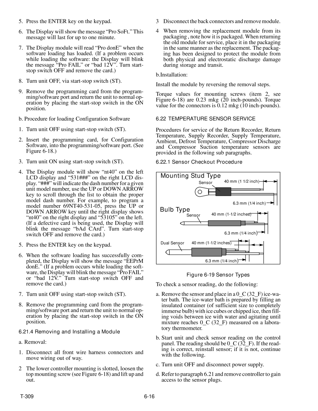
Procedures for service of the Return Recorder, Return Temperature, Supply Recorder, Supply Temperature, Ambient, Defrost Temperature, Compressor Discharge and Compressor Suction temperature sensors are provided in the following sub paragraphs.

6.22.1 Sensor Checkout Procedure

Mounting Stud Type

40 mm (1 1/2 inch)


Sensor


Bulb Type


6.3 mm (1/4 inch)

40 mm (1-1/2 inches)


Sensor


6.3 mm (1/4 inch)

Dual Sensor

40 mm (1-1/2 inches)


6.3 mm (1/4 inch)

Figure 6-19 Sensor Types

To check a sensor reading, do the following:

a.Remove the sensor and place in a 0_C (32_F) ice-wa- ter bath. The ice-water bath is prepared by filling an insulated container (of sufficient size to completely immerse bulb) with ice cubes or chipped ice, then fill- ing voids between ice with water and agitating until mixture reaches 0_C (32_F) measured on a labora- tory thermometer.

b.Start unit and check sensor reading on the control panel. The reading should be 0_C (32_F). If the read- ing is correct, reinstall sensor; if it is not, continue with the following.

c.Turn unit OFF and disconnect power supply.

d.Refer to paragraph 6.21 and remove controller to gain access to the sensor plugs.

T-309

6-16

Page 80
Image 80
Carrier 69NT20-531-300 manual Mounting Stud Type

69NT20-531-300 specifications

The Carrier 69NT20-531-300 is a cutting-edge rooftop unit designed to meet the demanding requirements of commercial heating and cooling applications. This model embodies Carrier’s commitment to energy efficiency, reliability, and advanced technological features that enhance indoor comfort while minimizing operational costs.

One of the standout features of the Carrier 69NT20-531-300 is its high energy efficiency. It is equipped with advanced compressor technology that optimizes performance while reducing energy consumption. This ensures that businesses can maintain a comfortable indoor climate without incurring exorbitant utility bills. With a high Seasonal Energy Efficiency Ratio (SEER) and Energy Efficiency Ratio (EER), users can expect not only enhanced comfort but also significant cost savings over time.

The cooling capabilities of the 69NT20-531-300 are complemented by its robust heating options. This unit utilizes a gas heat exchanger, ensuring quick and even heating throughout the space. The combination of cooling and heating capabilities in one compact unit makes it a versatile choice for various applications, including retail spaces, offices, and warehouses.

In addition to its impressive performance specifications, the Carrier 69NT20-531-300 incorporates innovative technologies that further enhance its functionality. The unit comes with advanced controls, allowing for precise temperature regulation and zoning capabilities. This ensures that different areas of a building can maintain their desired temperatures based on usage, improving overall energy efficiency.

Durability is another hallmark of the Carrier 69NT20-531-300. The unit is constructed with high-quality materials and features a weather-proof cabinet that protects it from the elements, ensuring long-term reliability even in harsh conditions. Furthermore, its modular design simplifies maintenance, making it easy for technicians to access critical components.

The 69NT20-531-300 is also designed with low noise operation in mind. It employs sound-dampening technology to ensure that operations are quiet, making it an ideal choice for locations where noise reduction is a priority, such as schools or healthcare facilities.

Overall, the Carrier 69NT20-531-300 stands out as a premier choice for businesses looking for an efficient, reliable, and feature-rich rooftop HVAC unit. Its blend of energy efficiency, advanced technology, and durability positions it as a leader in commercial heating and cooling solutions, making it a valuable investment for any commercial property.