system can be charged. Oil can also be added to the system.

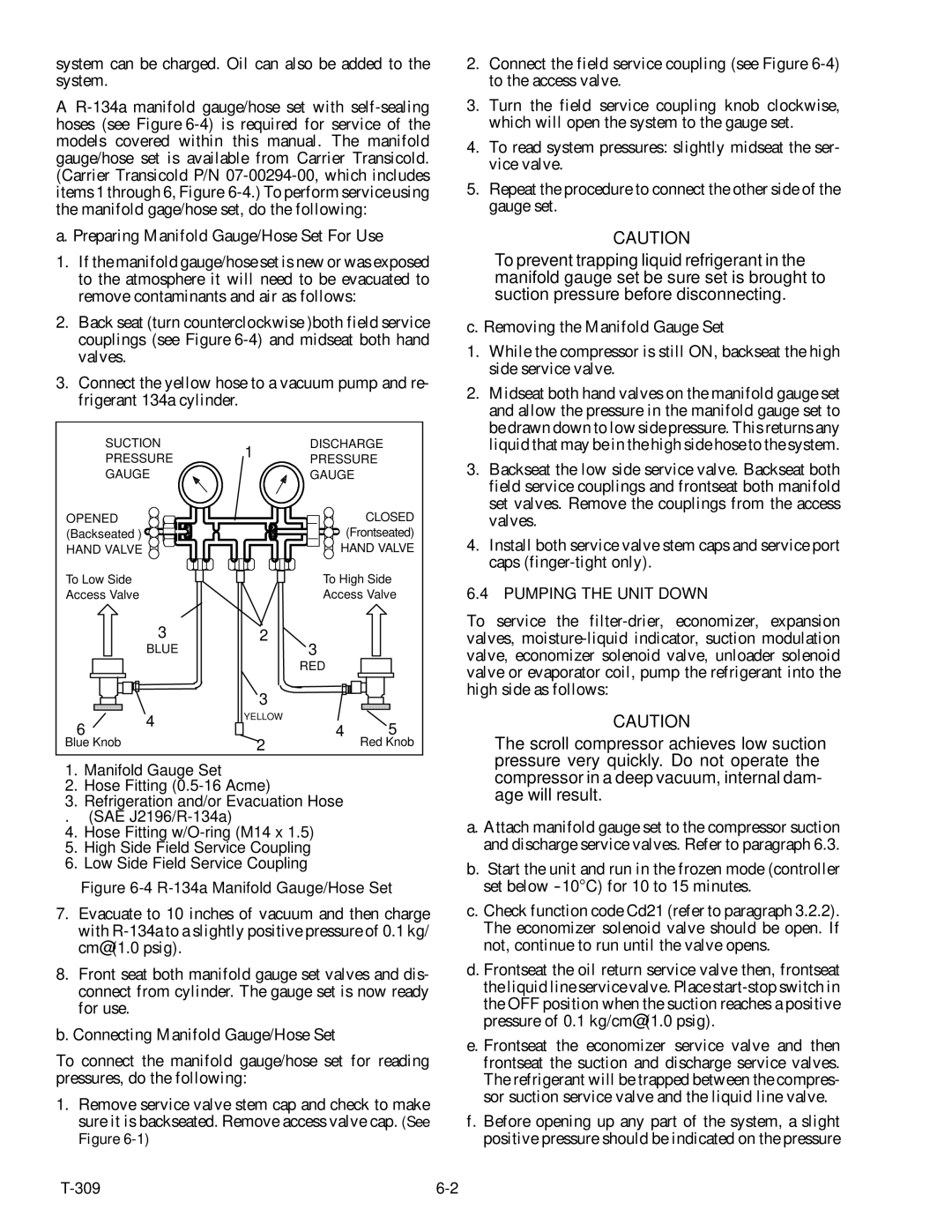
A R-134a manifold gauge/hose set with self-sealing hoses (see Figure 6-4) is required for service of the models covered within this manual. The manifold gauge/hose set is available from Carrier Transicold. (Carrier Transicold P/N 07-00294-00, which includes items 1 through 6, Figure 6-4.) To perform service using the manifold gage/hose set, do the following:

a. Preparing Manifold Gauge/Hose Set For Use

1.If the manifold gauge/hose set is new or was exposed to the atmosphere it will need to be evacuated to remove contaminants and air as follows:

2.Back seat (turn counterclockwise )both field service couplings (see Figure 6-4) and midseat both hand valves.

3.Connect the yellow hose to a vacuum pump and re- frigerant 134a cylinder.

SUCTION

1

DISCHARGE

PRESSURE

PRESSURE


GAUGE


GAUGE

OPENED

CLOSED

(Backseated )

(Frontseated)

HAND VALVE

HAND VALVE

2.Connect the field service coupling (see Figure 6-4) to the access valve.

3.Turn the field service coupling knob clockwise, which will open the system to the gauge set.

4.To read system pressures: slightly midseat the ser- vice valve.

5.Repeat the procedure to connect the other side of the gauge set.

CAUTION

To prevent trapping liquid refrigerant in the manifold gauge set be sure set is brought to suction pressure before disconnecting.

c. Removing the Manifold Gauge Set

1.While the compressor is still ON, backseat the high side service valve.

2.Midseat both hand valves on the manifold gauge set and allow the pressure in the manifold gauge set to be drawn down to low side pressure. This returns any liquid that may be in the high side hose to the system.

3.Backseat the low side service valve. Backseat both field service couplings and frontseat both manifold set valves. Remove the couplings from the access valves.

4.Install both service valve stem caps and service port caps (finger-tight only).

To Low Side

Access Valve

3

BLUE

6

4


Blue Knob


To High Side

Access Valve

2

3


RED


3


YELLOW

4

5


2

Red Knob

6.4 PUMPING THE UNIT DOWN

To service the filter-drier, economizer, expansion valves, moisture-liquid indicator, suction modulation valve, economizer solenoid valve, unloader solenoid valve or evaporator coil, pump the refrigerant into the high side as follows:

CAUTION

The scroll compressor achieves low suction pressure very quickly. Do not operate the

1.Manifold Gauge Set

2.Hose Fitting (0.5-16 Acme)

3.Refrigeration and/or Evacuation Hose

. (SAE J2196/R-134a)

4.Hose Fitting w/O-ring (M14 x 1.5)

5.High Side Field Service Coupling

6.Low Side Field Service Coupling

Figure 6-4 R-134a Manifold Gauge/Hose Set

7.Evacuate to 10 inches of vacuum and then charge with R-134a to a slightly positive pressure of 0.1 kg/ cm@ (1.0 psig).

8.Front seat both manifold gauge set valves and dis- connect from cylinder. The gauge set is now ready for use.

b. Connecting Manifold Gauge/Hose Set

To connect the manifold gauge/hose set for reading pressures, do the following:

1.Remove service valve stem cap and check to make sure it is backseated. Remove access valve cap. (See Figure 6-1)

compressor in a deep vacuum, internal dam- age will result.

a.Attach manifold gauge set to the compressor suction and discharge service valves. Refer to paragraph 6.3.

b.Start the unit and run in the frozen mode (controller set below -10°C) for 10 to 15 minutes.

c.Check function code Cd21 (refer to paragraph 3.2.2). The economizer solenoid valve should be open. If not, continue to run until the valve opens.

d.Frontseat the oil return service valve then, frontseat the liquid line service valve. Place start-stop switch in the OFF position when the suction reaches a positive pressure of 0.1 kg/cm@ (1.0 psig).

e.Frontseat the economizer service valve and then frontseat the suction and discharge service valves. The refrigerant will be trapped between the compres- sor suction service valve and the liquid line valve.

f.Before opening up any part of the system, a slight positive pressure should be indicated on the pressure

T-309

6-2

Page 66
Image 66
Carrier 69NT20-531-300 manual Compressor in a deep vacuum, internal dam- age will result

69NT20-531-300 specifications

The Carrier 69NT20-531-300 is a cutting-edge rooftop unit designed to meet the demanding requirements of commercial heating and cooling applications. This model embodies Carrier’s commitment to energy efficiency, reliability, and advanced technological features that enhance indoor comfort while minimizing operational costs.

One of the standout features of the Carrier 69NT20-531-300 is its high energy efficiency. It is equipped with advanced compressor technology that optimizes performance while reducing energy consumption. This ensures that businesses can maintain a comfortable indoor climate without incurring exorbitant utility bills. With a high Seasonal Energy Efficiency Ratio (SEER) and Energy Efficiency Ratio (EER), users can expect not only enhanced comfort but also significant cost savings over time.

The cooling capabilities of the 69NT20-531-300 are complemented by its robust heating options. This unit utilizes a gas heat exchanger, ensuring quick and even heating throughout the space. The combination of cooling and heating capabilities in one compact unit makes it a versatile choice for various applications, including retail spaces, offices, and warehouses.

In addition to its impressive performance specifications, the Carrier 69NT20-531-300 incorporates innovative technologies that further enhance its functionality. The unit comes with advanced controls, allowing for precise temperature regulation and zoning capabilities. This ensures that different areas of a building can maintain their desired temperatures based on usage, improving overall energy efficiency.

Durability is another hallmark of the Carrier 69NT20-531-300. The unit is constructed with high-quality materials and features a weather-proof cabinet that protects it from the elements, ensuring long-term reliability even in harsh conditions. Furthermore, its modular design simplifies maintenance, making it easy for technicians to access critical components.

The 69NT20-531-300 is also designed with low noise operation in mind. It employs sound-dampening technology to ensure that operations are quiet, making it an ideal choice for locations where noise reduction is a priority, such as schools or healthcare facilities.

Overall, the Carrier 69NT20-531-300 stands out as a premier choice for businesses looking for an efficient, reliable, and feature-rich rooftop HVAC unit. Its blend of energy efficiency, advanced technology, and durability positions it as a leader in commercial heating and cooling solutions, making it a valuable investment for any commercial property.