®3
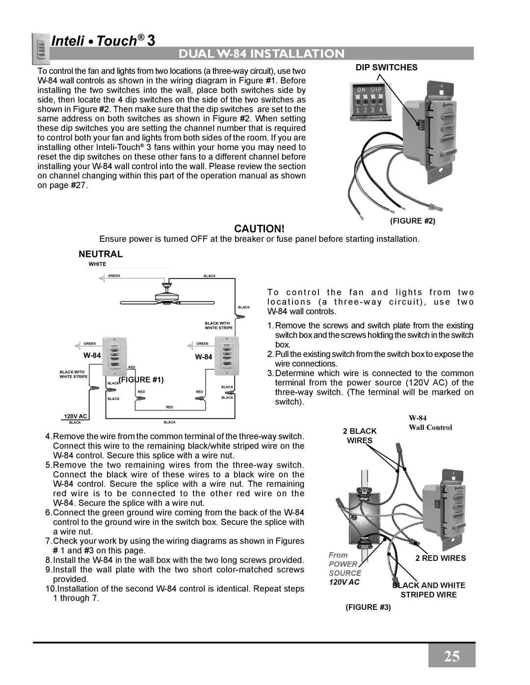
dual W-84 Installation
To control the fan and lights from two locations (a
CAUTION!
DIP SWITCHES
(FIGURE #2)
Ensure power is turned OFF at the breaker or fuse panel before starting installation.
NEUTRAL
WHITE
GREEN | BLACK |
BLACK
| BLACK WITH |
| WHITE STRIPE |
GREEN | GREEN |
RED |
|
BLACK WITH |
|
WHITE STRIPE |
|
BLACK(FIGURE #1) | BLACK |
| |
RED | RED |
BLACK | BLACK |
| RED |
T o c o n t r o l t h e f a n a n d l i g h t s f r o m t w o locations (a three - way circuit), use t w o
1.Remove the screws and switch plate from the existing switch box and the screws holding the switch in the switch box.
2.Pull the existing switch from the switch box to expose the wire connections.
3.Determine which wire is connected to the common terminal from the power source (120V AC) of the
120V AC
BLACK | BLACK |
4.Remove the wire from the common terminal of the
5.Remove the two remaining wires from the
6.Connect the green ground wire coming from the back of the
7.Check your work by using the wiring diagrams as shown in Figures
#1 and #3 on this page.
8.Install the
provided.
10.Installation of the second
2 BLACK Wall Control
WIRES
2 RED WIRES
BLACK AND WHITE
STRIPED WIRE
(FIGURE #3)
25