Chapter 2 Installing the Access Point
Deploying the Access Points on the Wireless Network
Step 4 For lightweight access points, after your access points are deployed, ensure that your controller is not configured as a master controller. A master controller should only be used for configuring access points and not in a working network.
Access Point Layout and Connectors
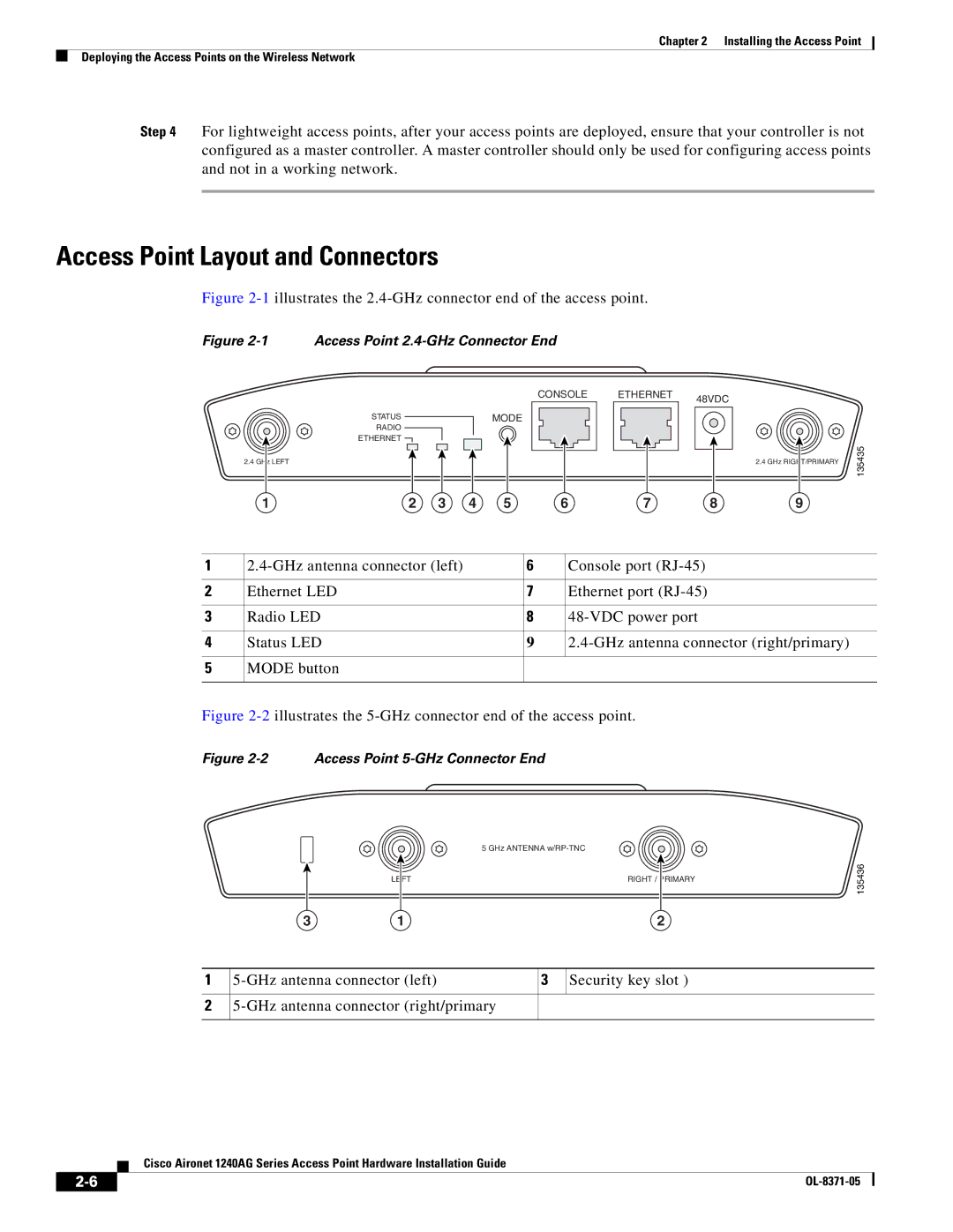
Figure 2-1 illustrates the 2.4-GHz connector end of the access point.
Figure 2-1 Access Point 2.4-GHz Connector End
| CONSOLE | ETHERNET | 48VDC |
|
|
| |
STATUS | MODE |
|
|
RADIO |
|
|
|
ETHERNET |
|
|
|
2.4 GHz LEFT
1 | 2 | 3 | 4 | 5 | 6 | 7 | 8 |
2.4 GHz RIGHT/PRIMARY
9
135435
1 | 6 | Console port | |
|
|
|
|
2 | Ethernet LED | 7 | Ethernet port |
|
|
|
|
3 | Radio LED | 8 | |
|
|
|
|
4 | Status LED | 9 | |
|
|
|
|
5 | MODE button |
|
|
|
|
|
|
Figure 2-2 illustrates the 5-GHz connector end of the access point.
Figure 2-2 Access Point 5-GHz Connector End
5 GHz ANTENNA
LEFT | RIGHT / | PRIMARY |
|
|
|
135436
3 | 1 | 2 |
1
2
3 | Security key slot ) | |
|
|
|
Cisco Aironet 1240AG Series Access Point Hardware Installation Guide
|
| |
|