Cisco Systems 3650 manual Stripping the Ground Wire

Models: 3650

1 94
Download 94 pages 29.69 Kb
Page 55
Image 55

Chapter 3 Power Supply Installation

Installing a DC Power Supply

Warning When installing or replacing the unit, the ground connection must always be made first and disconnected last. Statement 1046

Caution Follow the grounding procedure instructions, and use a UL-listed lug (included in the accessory kit).

Follow these steps to install either a single-hole ground lug or a dual-hole ground lug on the switch. Make sure to follow any grounding requirements at your site.

Step 1 Use the ground lug screw and the lug ring for a
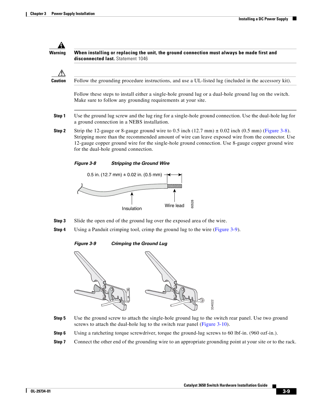
 single-hole ground connection. Use the dual-hole lug for a ground connection in a NEBS installation.

Step 2 Strip the 12-gauge or 8-gauge ground wire to 0.5 inch (12.7 mm) ± 0.02 inch (0.5 mm) (Figure 3-8). Stripping more than the recommended amount of wire can leave exposed wire from the connector. Use 12-gauge copper ground wire for the single-hole ground connection. Use 8-gauge copper ground wire for the dual-hole ground connection.

Figure 3-8 Stripping the Ground Wire

0.5 in. (12.7 mm) ± 0.02 in. (0.5 mm)

Insulation

Wire lead

60528

Step 3 Slide the open end of the ground lug over the exposed area of the wire.

Step 4 Using a Panduit crimping tool, crimp the ground lug to the wire (Figure 3-9).

Figure 3-9 Crimping the Ground Lug

334022

Step 5 Use the ground screw to attach the single-hole ground lug to the switch rear panel. Use two ground screws to attach the dual-hole lug to the switch rear panel (Figure 3-10).

Step 6 Using a ratcheting torque screwdriver, torque the ground-lug screws to 60 lbf-in. (960 ozf-in.).

Step 7 Connect the other end of the grounding wire to an appropriate grounding point at your site or to the rack.

Catalyst 3650 Switch Hardware Installation Guide


OL-29734-01

3-9


Page 55
Image 55
Cisco Systems 3650 manual Stripping the Ground Wire