Chapter 2 Switch Installation
Installing and Removing SFP and SFP+ Modules
Warning Class 1 laser product. Statement 1008
•Do not remove the dust plugs from the SFP modules or the rubber caps from the
•Removing and installing an SFP module can shorten its useful life. Do not remove and insert any SFP module more often than is necessary.
•To prevent ESD damage, follow your normal board and component handling procedures when connecting cables to the switch and other devices.
Observe these precautions:
Step 1 Attach an
On some SFP modules, the send and receive (TX and RX) markings might be shown by arrows that show the direction of the connection.
Step 3 If the SFP module has a
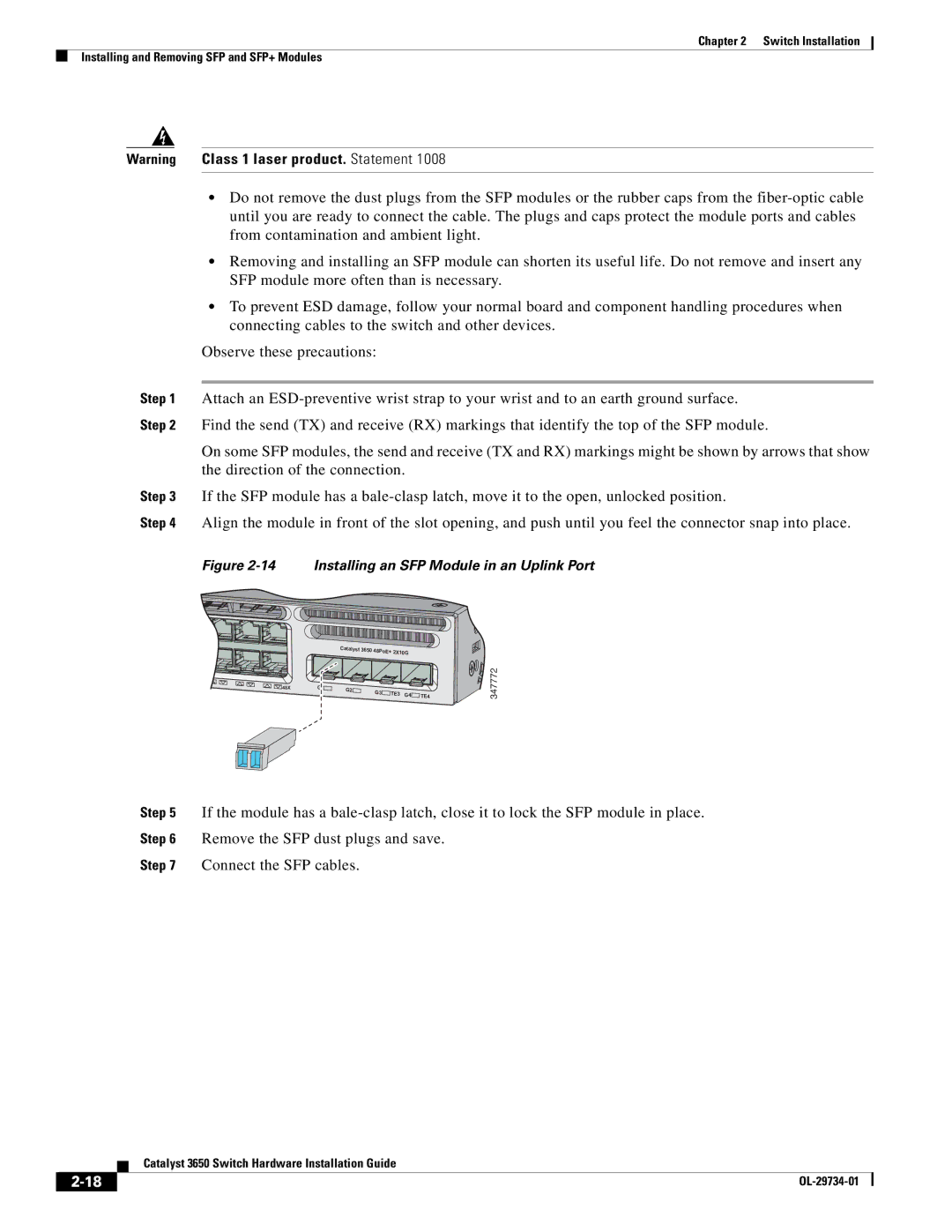
Step 4 Align the module in front of the slot opening, and push until you feel the connector snap into place.
Figure 2-14 Installing an SFP Module in an Uplink Port
![]()
![]()
![]()
![]() 48X
48X
| Catalyst 3650 | 48PoE+ 2X10G |
| ||
|
|
| |||
G1 | G2 | G3 | TE3 | G4 |
|
| TE4 | ||||
|
| ||||
|
|
|
| ||
![]()
![]()
![]()
![]()
![]() 347772
347772
Step 5 If the module has a
Step 6 Remove the SFP dust plugs and save.
Step 7 Connect the SFP cables.
| Catalyst 3650 Switch Hardware Installation Guide |
|
