Chapter 3 Power Supply Installation
Power Supply Module Overview
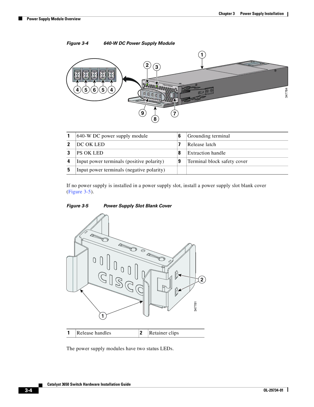
Figure 3-4 640-W DC Power Supply Module
1
2 3
DC OK |
|
|
PS OK | ||
|
| |
|
| 640WDC |
4 5 6 5 4
9 7
8
347784
1 | 6 | Grounding terminal | |
|
|
|
|
2 | DC OK LED | 7 | Release latch |
|
|
|
|
3 | PS OK LED | 8 | Extraction handle |
|
|
|
|
4 | Input power terminals (positive polarity) | 9 | Terminal block safety cover |
|
|
|
|
5 | Input power terminals (negative polarity) |
|
|
|
|
|
|
If no power supply is installed in a power supply slot, install a power supply slot blank cover (Figure
Figure 3-5 Power Supply Slot Blank Cover
1
2
347781
1
Release handles
2
Retainer clips
The power supply modules have two status LEDs.
Catalyst 3650 Switch Hardware Installation Guide
|
| |
|