Chapter 3 Power Supply Installation
Installation Guidelines
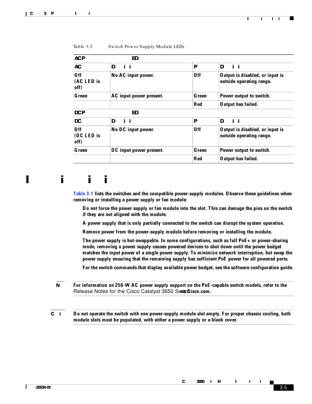
Table | Switch Power Supply Module LEDs |
|
| |
|
|
| ||
AC Power Supply Module LEDs |
|
| ||
|
|
|
|
|
AC OK |
| Description | PS OK | Description |
|
|
|
|
|
Off |
| No AC input power. | Off | Output is disabled, or input is |
(AC LED is |
|
|
| outside operating range. |
off) |
|
|
|
|
|
|
|
|
|
Green |
| AC input power present. | Green | Power output to switch. |
|
|
|
|
|
|
|
| Red | Output has failed. |
|
|
|
| |
DC Power Supply Module LEDs |
|
| ||
|
|
|
|
|
DC OK |
| Description | PS OK | Description |
|
|
|
|
|
Off |
| No DC input power. | Off | Output is disabled, or input is |
(DC LED is |
|
|
| outside operating range. |
off) |
|
|
|
|
|
|
|
|
|
Green |
| DC input power present. | Green | Power output to switch. |
|
|
|
|
|
|
|
| Red | Output has failed. |
|
|
|
|
|
Installation Guidelines
Table
•Do not force the power supply or fan module into the slot. This can damage the pins on the switch if they are not aligned with the module.
•A power supply that is only partially connected to the switch can disrupt the system operation.
•Remove power from the
•The power supply is
For the switch commands that display available power budget, see the software configuration guide.
Note For information on
Caution Do not operate the switch with one
Catalyst 3650 Switch Hardware Installation Guide
|
| ||
|
|