Install Field Replaceable Units (FRUs)
For the
40
OT SHIP WITH POWER SUPPLY ALLED
INPUT VOLTAGE :
FASTENER TO BE FULLY ENGAGED
BEFORE OPERATING POWER SUPPLY
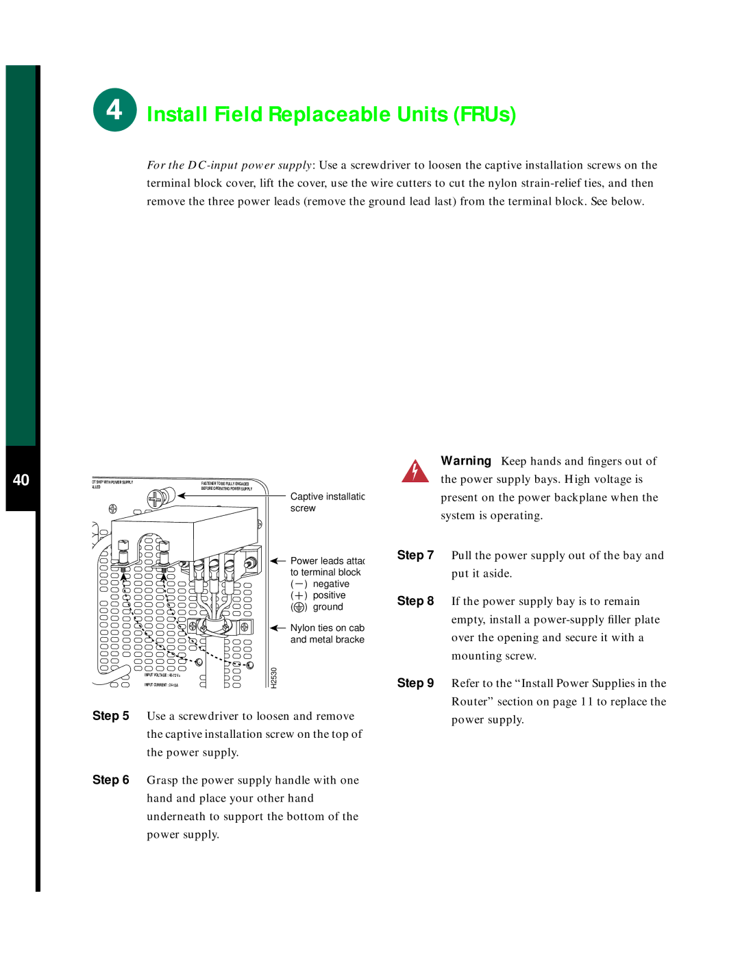
Captive installatio screw
![]() Power leads attac to terminal block ( ) negative
Power leads attac to terminal block ( ) negative
( ![]() ) positive (
) positive (![]() ) ground
) ground
Nylon ties on cab and metal bracke
H2530
Warning Keep hands and fingers out of the power supply bays. High voltage is present on the power backplane when the system is operating.
Step 7 Pull the power supply out of the bay and put it aside.
Step 8 If the power supply bay is to remain empty, install a
Step 9 Refer to the “Install Power Supplies in the Router” section on page 11 to replace the
Step 5 Use a screwdriver to loosen and remove the captive installation screw on the top of the power supply.
Step 6 Grasp the power supply handle with one hand and place your other hand underneath to support the bottom of the power supply.
power supply.