SRB Configuration Examples
LNM for a More Complex Network Example
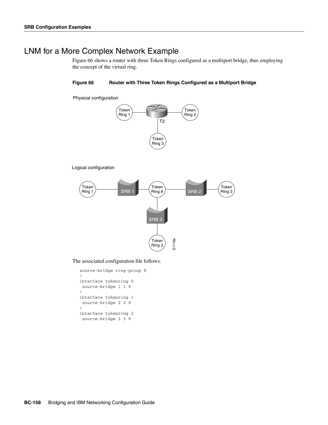
Figure 66 shows a router with three Token Rings configured as a multiport bridge, thus employing the concept of the virtual ring.
Figure 66 Router with Three Token Rings Configured as a Multiport Bridge
Physical configuration
Token | T0 | T1 | Token |
Ring 1 | Ring 2 |
T2
Token
Ring 3
Logical configuration
Token | SRB 1 | Token | SRB 2 | Token |
Ring 1 | Ring 8 | Ring 2 |
SRB 3
Token
Ring 3
The associated configuration file follows.
source-bridge ring-group 8
!
interface tokenring 0
!
interface tokenring 1
!
interface tokenring 2
S1116a
