|
|
|
| |
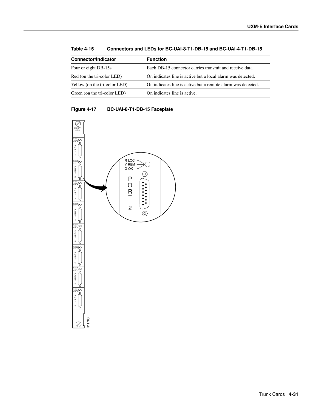
| Table | Connectors and LEDs for | ||
|
|
|
| |
| Connector/Indicator | Function | ||
|
|
|
| |
| Four or eight | Each | ||
|
|
|
| |
| Red (on the | On indicates line is active but a local alarm was detected. | ||
|
|
|
| |
| Yellow (on the | On indicates line is active but a remote alarm was detected. | ||
|
|
|
| |
| Green (on the | On indicates line is active. | ||
|
|
|
| |
| Figure |
| ||
DB15
R LOC Y REM G OK
P
O
R
T
1
R LOC Y REM G OK
P
O
R
T
2
R LOC Y REM G OK
P
O
R
T
3
R LOC Y REM G OK
P
O
R
T
4
R LOC Y REM G OK
P
O
R
T
5
R LOC Y REM G OK
P
O
R
T
6
R LOC Y REM G OK
P
O
R
T
7
R LOC Y REM G OK
P
O
R
T
8
RLOC Y REM G OK
P
O
R
T
2
H11703
Trunk Cards
