Universal Switching Module Enhanced
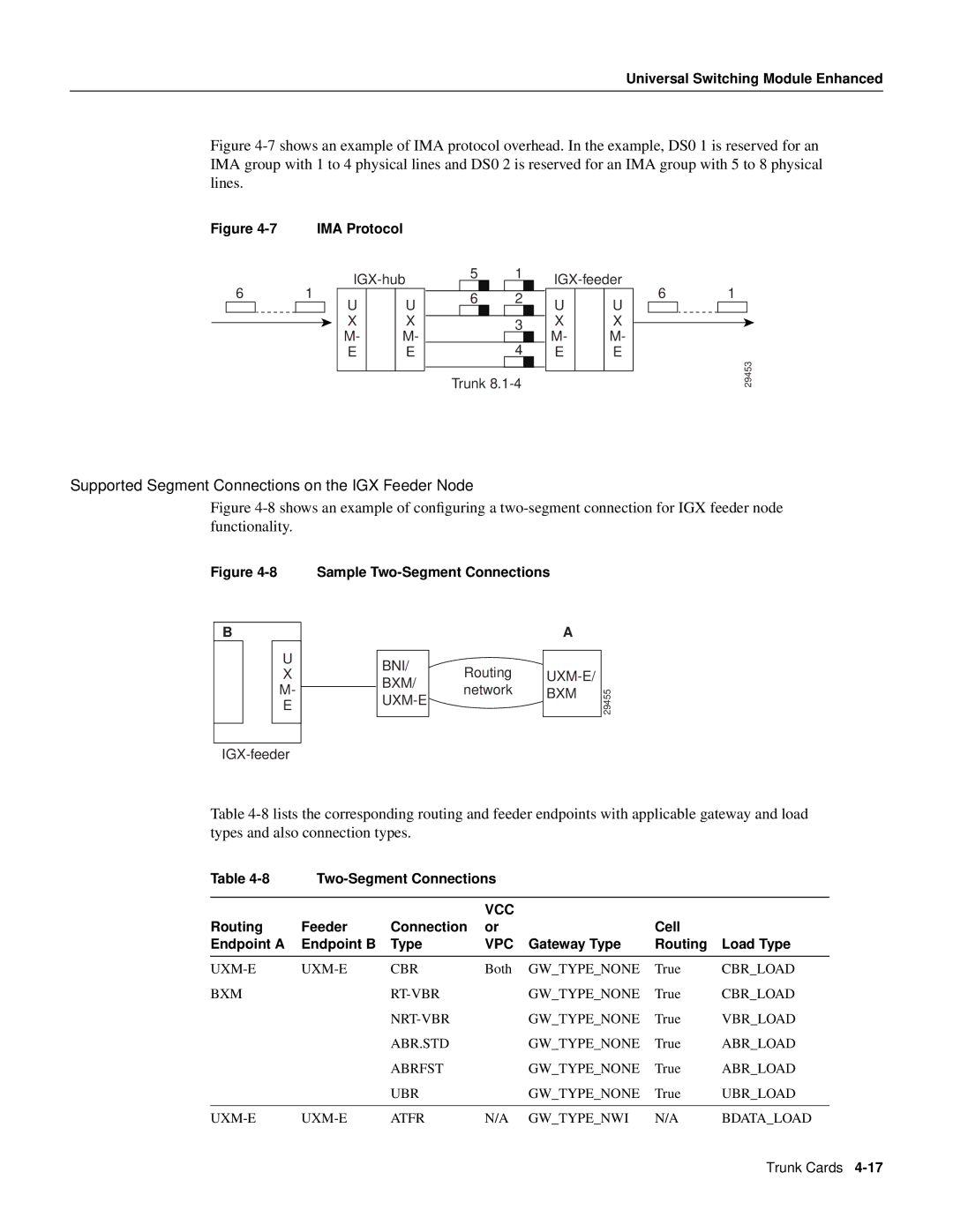
Figure 4-7 shows an example of IMA protocol overhead. In the example, DS0 1 is reserved for an IMA group with 1 to 4 physical lines and DS0 2 is reserved for an IMA group with 5 to 8 physical lines.
Figure | IMA Protocol |
6 1
U |
| U |
X |
| X |
M- |
| M- |
E |
| E |
|
|
|
51
62
3
4
Trunk
U |
| U |
X |
| X |
M- |
| M- |
E |
| E |
|
|
|
6 1
29453
Supported Segment Connections on the IGX Feeder Node
Figure 4-8 shows an example of configuring a two-segment connection for IGX feeder node functionality.
Figure 4-8 Sample Two-Segment Connections
B
U
X
M-
E
BNI/
BXM/
Routing network
A
| |
BXM | 29455 |
|
Table
Table |
|
|
|
| ||
|
|
|
|
|
|
|
|
|
| VCC |
|
|
|
Routing | Feeder | Connection | or |
| Cell |
|
Endpoint A | Endpoint B | Type | VPC | Gateway Type | Routing | Load Type |
|
|
|
|
|
|
|
CBR | Both | GW_TYPE_NONE | True | CBR_LOAD | ||
BXM |
|
| GW_TYPE_NONE | True | CBR_LOAD | |
|
|
| GW_TYPE_NONE | True | VBR_LOAD | |
|
| ABR.STD |
| GW_TYPE_NONE | True | ABR_LOAD |
|
| ABRFST |
| GW_TYPE_NONE | True | ABR_LOAD |
|
| UBR |
| GW_TYPE_NONE | True | UBR_LOAD |
|
|
|
|
|
|
|
ATFR | N/A | GW_TYPE_NWI | N/A | BDATA_LOAD | ||
Trunk Cards