www.ti.com
Introduction
1.3Functional Block Diagram
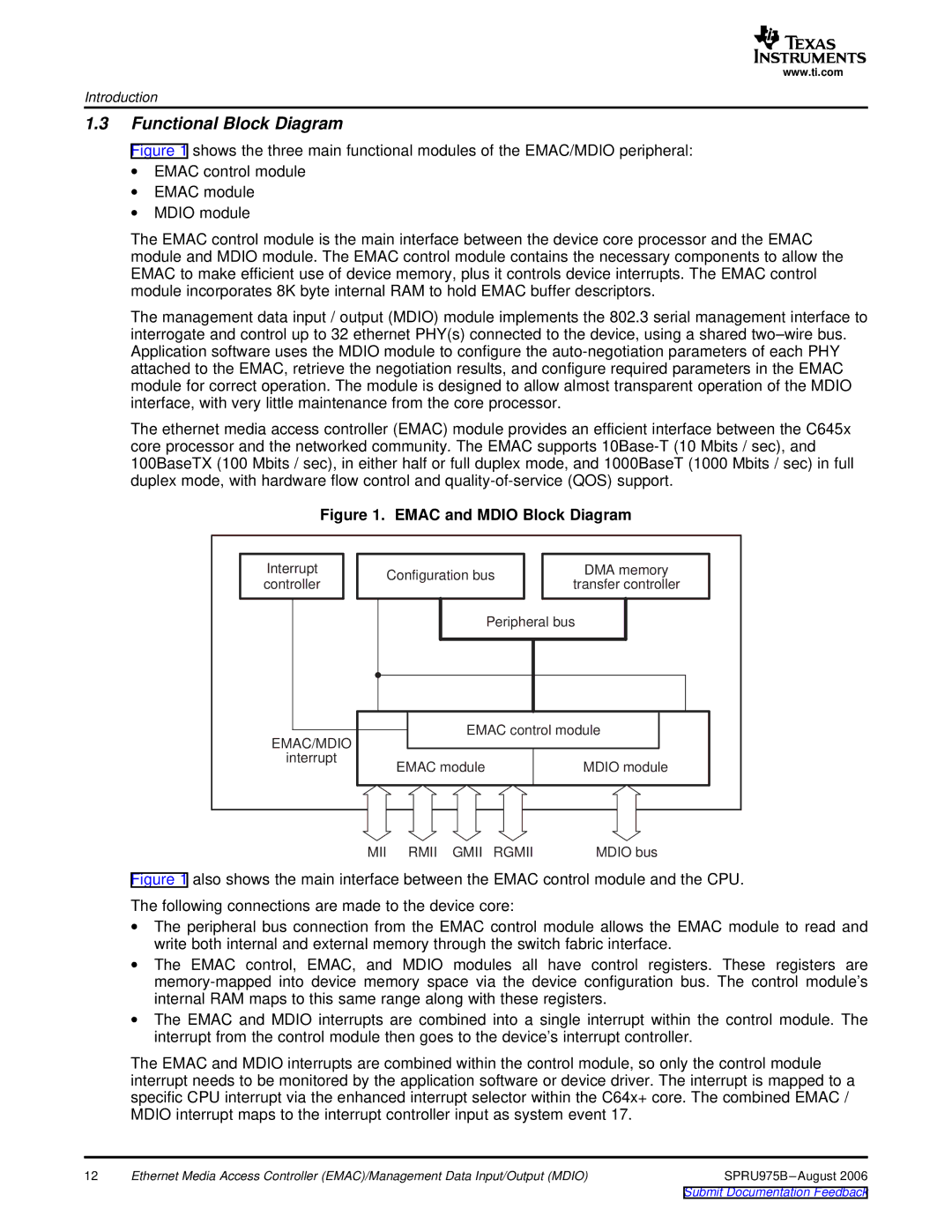
Figure 1 shows the three main functional modules of the EMAC/MDIO peripheral:
∙EMAC control module
∙EMAC module
∙MDIO module
The EMAC control module is the main interface between the device core processor and the EMAC module and MDIO module. The EMAC control module contains the necessary components to allow the EMAC to make efficient use of device memory, plus it controls device interrupts. The EMAC control module incorporates 8K byte internal RAM to hold EMAC buffer descriptors.
The management data input / output (MDIO) module implements the 802.3 serial management interface to interrogate and control up to 32 ethernet PHY(s) connected to the device, using a shared two–wire bus. Application software uses the MDIO module to configure the auto-negotiation parameters of each PHY attached to the EMAC, retrieve the negotiation results, and configure required parameters in the EMAC module for correct operation. The module is designed to allow almost transparent operation of the MDIO interface, with very little maintenance from the core processor.
The ethernet media access controller (EMAC) module provides an efficient interface between the C645x core processor and the networked community. The EMAC supports 10Base-T (10 Mbits / sec), and 100BaseTX (100 Mbits / sec), in either half or full duplex mode, and 1000BaseT (1000 Mbits / sec) in full duplex mode, with hardware flow control and quality-of-service (QOS) support.
Figure 1. EMAC and MDIO Block Diagram
Interrupt | Configuration bus |
| DMA memory | ||
controller | transfer controller | ||||
|
| ||||
|
| Peripheral bus |
| ||
EMAC/MDIO | EMAC control module | ||||
|
|
|
| ||
interrupt | EMAC module |
|
| MDIO module | |
|
|
| |||
MII RMII GMII RGMII | MDIO bus |
Figure 1 also shows the main interface between the EMAC control module and the CPU.
The following connections are made to the device core:
∙The peripheral bus connection from the EMAC control module allows the EMAC module to read and write both internal and external memory through the switch fabric interface.
∙The EMAC control, EMAC, and MDIO modules all have control registers. These registers are memory-mapped into device memory space via the device configuration bus. The control module’s internal RAM maps to this same range along with these registers.
∙The EMAC and MDIO interrupts are combined into a single interrupt within the control module. The interrupt from the control module then goes to the device’s interrupt controller.
The EMAC and MDIO interrupts are combined within the control module, so only the control module interrupt needs to be monitored by the application software or device driver. The interrupt is mapped to a specific CPU interrupt via the enhanced interrupt selector within the C64x+ core. The combined EMAC / MDIO interrupt maps to the interrupt controller input as system event 17.
12 | Ethernet Media Access Controller (EMAC)/Management Data Input/Output (MDIO) | SPRU975B |